Power cable, Mobile antenna, 1) antenna installation – Kenwood TS-130SE User Manual
Page 15: Notes, 2) coaxial cable connection (fig. 4-10), 3) antenna adjustment (fig. 4-11), Noise reduction
Attention! The text in this document has been recognized automatically. To view the original document, you can use the "Original mode".
POWER CABLE
red and white ©
black and gray 0
Connect the TS130SE power cable to the battery ter
minals, with consideration to current requirements and noise
prevention. The maximum current drawn by the TS-130SE
reaches to between 18 and 20A when transmitting.
Therefore, the cable should be made as short as possible, us
ing the specified fuse. Also, determine that the power
system of the car (including the battery and generator or
alternator) will handle the increased load of the TS-130SE.
Route battery and ANTENNA leads away from all high
voltage secondary circuits to prevent ignition noise in
terference.
4.8.3. MOBILE ANTENNA
(1) Antenna Installation
Use a rugged mount for the mobile antenna because HF
antennas are larger (and have more wind load) and are
heavier
than
VHF
antennas.
A
bumper
mount
is
recommended for general use. The ground side of the
mount must be grounded perfectly to the body of the car
since the body itself functions as the ground plane for the
mobile antenna. (Refer to Fig. 4-10.)
NOTES; -----------------------------------------------------------------------
1. Some cars have a urethande plastic bumper. For such
cars, ground the antenna mount to the body.
2. When tuning the newly installed antenna, use following
procedure:
•
Turn the CAR control fully counter-clockwise for
minimum transmit power.
•
With the transceiver in transmit mode, raise transmit
power output slowly by rotating the CAR control
clockwise. The antenna should be adjusted with mi
nimum power.
•
Transmitting with full power is recommended after
the antenna is adjusted for a VSWR below 1.5:1.
3. Antenna installation is critical for successful mobile
operation. For further information refer to THE RADIO
AMATEUR'S HANDBOOK, RADIO HANDBOOK, or
other texts.
(2) Coaxial Cable Connection (Fig. 4-10)
When the antenna is mounted on the vehicles bumper, the
coaxial cable from the antenna can be routed through a
drain hole in the trunk. When the antenna is roof mounted
pass the cable between the body and door. Leave a
drip-loop at the lowest point in the cable before entry into
the vehicle to prevent water from entering the car.
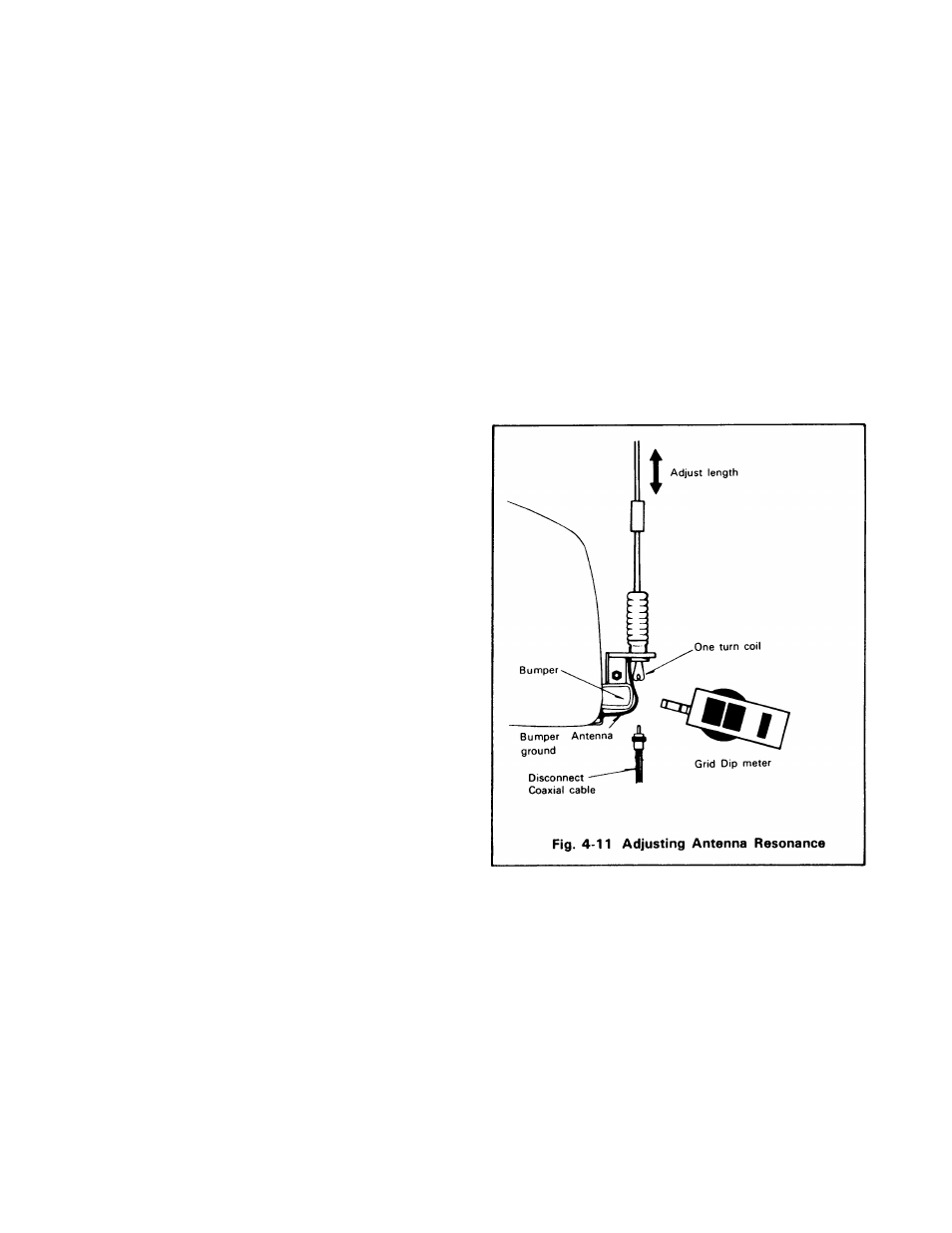
(3) Antenna Adjustment (Fig. 4-11)
Some mobile antennas are not designed for 50-ohm im
pedance. In this case, impedance matching between the
antenna and the coaxial cable (50Q) is required. This can
be achieved by using an antenna matching device or
coupler.
The antenna to be used should first be checked with a dip
meter to insure that it is designed for your operating band,
then the impedance matching should be checked with an
SWR meter. (See Fig. 4-11)
The VSWR should preferably be less than 1.5:1 for satisfac
tory operation. For antenna adjustment refer to the antenna
instruction manual.
4.8.4. NOISE REDUCTION
In motor vehicles, ignition noise is generated by the ignition
coil or distributor. Other sources of noise include the wiper
and heater motors.
Although the TS-130SE is equipped with a noise blanker
to minimize ignition noise, it is imperative that some preven
tive measures be taken to reduce the noise to the lowest
possible level.
15