Cw operation, Ts-130se, Fig. 4-4 testing with dummy load or power meter – Kenwood TS-130SE User Manual
Page 11: Final stage protection, Notes, 3) when fa-4 fan unit is installed, Mic gain control (fig. 4-5), Alc (automatic level control)
Attention! The text in this document has been recognized automatically. To view the original document, you can use the "Original mode".
10k — 33 ki2 (depending on micropone used.)
o------ ------------
•
---------- o
from microphone
O---------------
to the MIC connecter
-O
The MC-50 microphone is recommended (Microphone sen
sitivity; — 55 ±3dB for approx. 5 cm distance to the mic.i
• CW Operation
1
Set the MODE switch to CW and the meter switch to
ALC.
2
Set the standby switch to SEND and adjust the CAR
control so the meter deflects within the ALC zone. If a
key is connected, it should be depressed during the ad
justment.
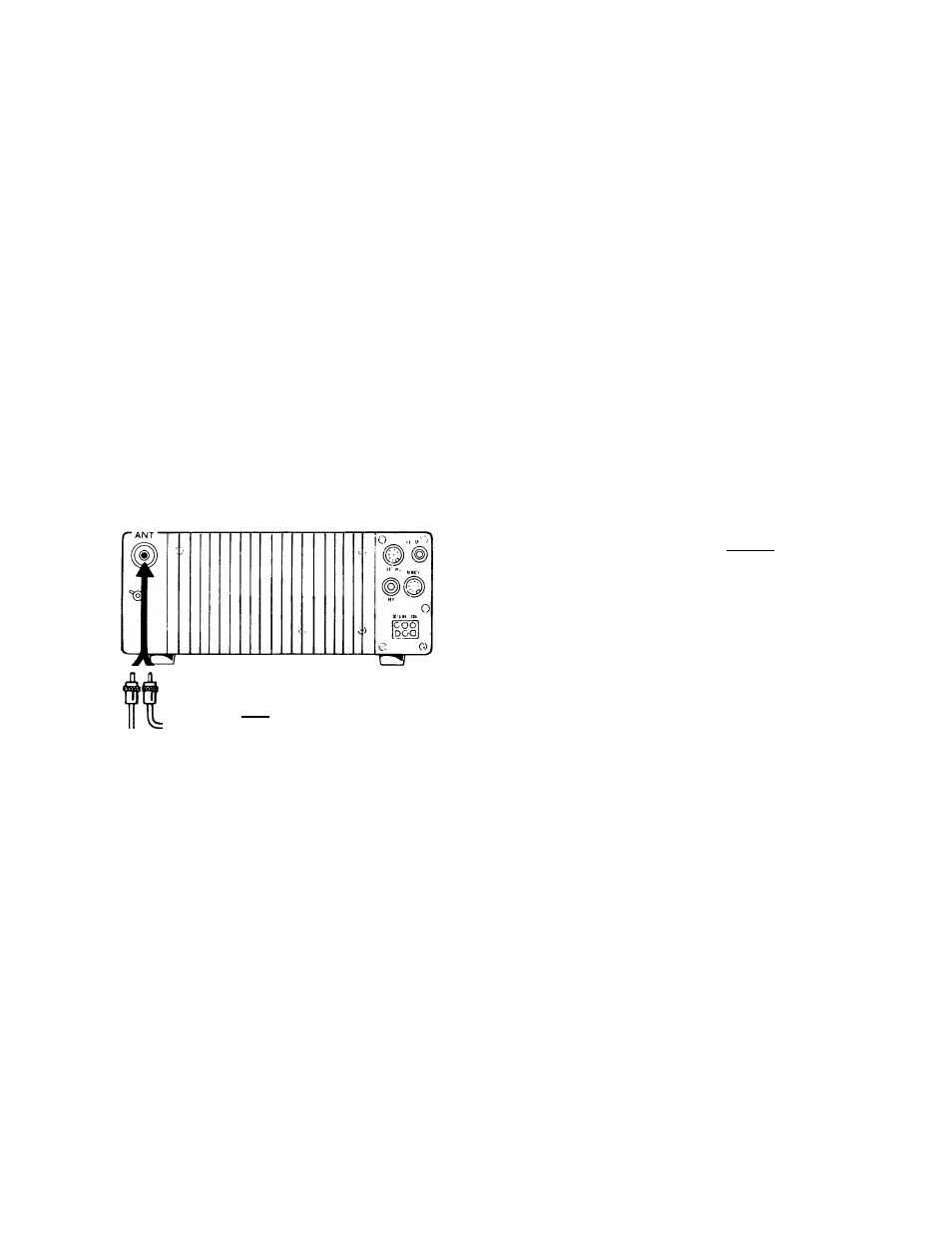
TS-130SE
in
Power meter
Dummy load
Fig. 4-4 Testing with Dummy Load or
Power Meter
4.2.1. FINAL STAGE PROTECTION
The TS-130SE features a VSWR protection circuit to protect
the final-amplifier transistors.
Two different protection circuits are designed into the TS-
130SE.
i)
The same VSWR protection method as used in the TS-
130SE. That is, the final-stage transistors are protected
by detecting VSWR of the antenna system and
automatically lowering transmitter output power if the
VSWR is too high.
ii)
The heat-sink temperature could rise abnormally during
long transmissions, if the area adjacent to the heat-sink
is blocked. In this case, the TS-130SE automatically
returns to the receiving mode, and transmitting is not
possible until the heat-sink cools to the proper
temperature.
NOTES:-------------------------------------------------------------------------
If transmitter output decreases due to activation of the
protection circuit caused by high VSWR, recheck and retune
the antenna system carefully.
(3) When FA-4 Fan Unit Is Installed.
The cooling fan operates when the heat-sink temperature
rises, to approximately
(122°F) and it ceases to
operate when the temperature decreases to normal, ap
proximately
(104°F). The heat-sink is made of
die-cast aluminum and is actually the rear panel. It must be
kept clear of surrounding objects, in order that heat will dis
sipate easily.
The cooling fan is designed to operate when the heat-sink
temperature is at a specific level, regardless of whether the
unit is in transmit or receive mode.
Fan life
IS
approximately 500 hours.
NOTES:-------------------------------------------------------------------------
When the cooling fan starts to operate, determine that ade
quate air flow is possible in the heat-sink area._____________
4.2.2. MIC G A I N CONTROL (Fig. 4-5)
This control adjusts the microphone input level When using
the TS-130SE in SSB mode, connect a microphone and
set the standby switch to SEND (antenna or dummy load
MUST be connected).
Set the meter switch to ALC and speak into the
microphone. Adjust the MIC GAIN control so the meter
does not deflect out of the ALC zone at signal peaks.
The TS-130SE accepts either a low or high impedance
microphone (500 ii to 50 k i i ) . When using a low impedance
microphone (500 i i ) the MIC GAIN control should be ad
vanced higher than when a high impedance microphone is
used, while observing the ALC meter.
• ALC (Automatic Level Control)
The ALC monitors the transmitter final stage output to
minimize
distortion
in
your
transmitted
signal.
It
automatically adjusts output to an optimum level.
11