Clarion ProAudio VRX 935VD VRX935VD User Manual
Page 59
VRX935VD
63
English
Installation and Wire
connection manual
VRX935VD
Installation and Wire connection manual
■ Contents
1. BEFORE STARTING ............................................................... 63
2. PACKAGE CONTENTS ........................................................... 63
3. GENERAL CAUTIONS ............................................................ 64
4. CAUTIONS ON INSTALLATION .............................................. 64
5. INSTALLING THE MAIN UNIT ................................................. 65
6. REMOVING THE MAIN UNIT .................................................. 67
7. CAUTIONS ON WIRING .......................................................... 67
8. WIRE CONNECTION .............................................................. 68
9. SAMPLE SYSTEMS ................................................................ 71
1.
BEFORE STARTING
2.
PACKAGE CONTENTS
1. This set is exclusively for use in cars with a
negative ground 12 V power supply.
2. Read these instructions carefully.
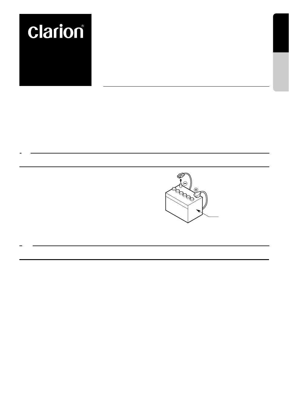
3. Be sure to disconnect the battery “-” termi-
nal before starting. This is to prevent short
circuits during installation. (Figure 1)
Car battery
Figure 1
1 Main unit
2 Tuner Amp unit
3 Manuals
Owner’s manual & Installation manual
Warranty card
4 Power supply lead (For the main unit)
5 Power supply lead (For the tuner amp
unit)
6 Connection cord (Main unit
↔ Tuner amp unit)
7 Antenna extension cord
8 Bag for accessories of the main unit (No. 1)
Flat head screw (M5
× 8) ............................ 4
Sems hexagonal bolt (M5
× 8) ..................... 5
Electro tap
Machine screw (M4
× 3) ............................... 4
9 Bag for accessories of the main unit (No. 2)
Hook plate ................................................... 2
Cord clamp
Rubber cap
Special screw
0 Bag for accessories of tuner amp unit
Maunting bracket ......................................... 2
Canoe clip ................................................... 4
Machine screw (M4
× 8) .............................. 4
! Universal mounting bracket
@ Remote control unit
# Battery
(for remote control unit)
$ Outer Escutcheon
% DCP Case