5. microprocessor backup, Lithium battery replacement, 7. ordering spare parts – Kenwood TM-521E User Manual
Page 19: 6. fuse replacement, 8. adjustments, Battery replacement, 7. ordering spare parts 5, Adjustments
Attention! The text in this document has been recognized automatically. To view the original document, you can use the "Original mode".
5-5. MICROPROCESSOR BACKUP
LITHIUM BATTERY REPLACEMENT
Lithium battery replacement should be performed by
an authorized KENWOOD service facility; either your
KENWOOD dealer, or the factory, since this unit con
tains CMOS type circuitry.
Notes:-----------------------------------------------------------------------
5-7. ORDERING SPARE PARTS
1
replaced,
using the
the
pro-
2.
When the lithium battery is
microprocessor must be reset,
cedure in Section 4-4-2.
When the lithium battery fails, the radio's
microcoded functions are not affected. Only in
formation stored in memory will be cleared.
5-6. FUSE REPLACEMENT
If the fuse blows;
DISCONNECT the AC Power Cable and replace
with the specified fuse only after determining the
cause, or contact either your KENWOOD dealer,
or the factory to repair the cause.
Warning:------------------------------------------------------------------------
1. Never connect the AC cable to the AC outlet un-
2
.
til fuse replacement has been made.
Never use a large amperage fuse. Replace with a
new fuse of the same rating.
This transceiver is equipped with the fuse(s) listed
below. If the fuse blows, determine the cause before
replacing the defective fuse. (Replacement fuses are
available from your authorized KENWOOD dealer.)
Fuse Location
Part Number
Q'ty
*13.8VDC Power
Input Cable
F05-1031-05 (10 A)
for TM-221/421 series only
1 ea.
F05-8021-05 (8 A)
for TM-321A and TM-521
series only
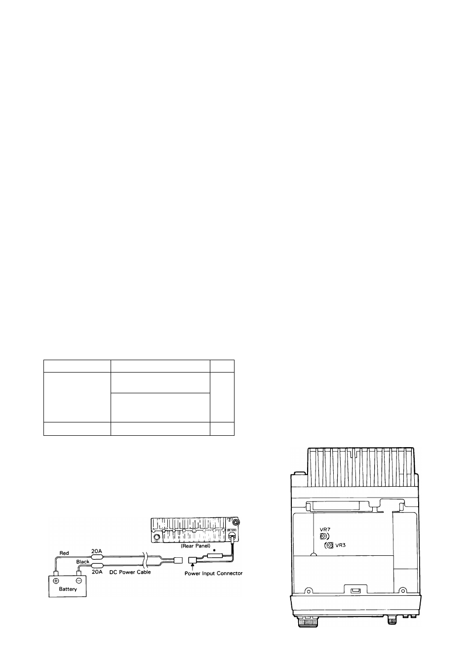
DC Power Cable
F05-2036-05 (20 A)
2 ea.
T ransceiver
When ordering replacement or spare parts for your
equipment, be sure to specify the following:
Model and serial number of your transceiver.
Schematic number of the part.
Printed circuit board number on which the part is
located.
Part number and name, if known, and quantity
desired.
Part numbers for most replacement parts is contain
ed in the service manual (available as an option from
your dealer).
5-8. ADJUSTMENTS
5-8-1. Cover Removal
Caution:------------------------------------------------------------------------
1. Before removing the top cover, turn the power
supply and radio POWER switches off, and
disconnect the Power Cable.
2. Do not pinch wiring when closing the cover.
1
Loosen the four screws on both the right and left
sides.
Remove the four screws attaching the top cover.
Remove the top cover and set aside.
Reverse steps 1 and 2 to reassemble the radio.
5-8-2. Low Power Output
Adjust VR7 on PC board to adjust the output of the
transceiver in the low power position. The adjust
ment range is 1 to 30 watts on the TM-221 series, 1
to 20 watts on the TM-321A and TM-421 series,
and 0.5 to 5 watts on the TM-521 series.
5-8-3. Microphone Gain
Adjust VR3 on PC board to the desired level.
Caution:------------------------------------------------------------
Too much microphone gain can cause reports of
audio distortion.
19
wm