0 shift indicator, D rev (reverse) indicator, D al (alert) indicator (tm-221es/421es only) – Kenwood TM-521E User Manual
Page 10: 0 scan indicator, 0 m (memory in) indicator, D memory channel number display, 0 ★ indicator, Q) on air indicator, Q) s & rf meter, 0 ant (antenna) connector
Attention! The text in this document has been recognized automatically. To view the original document, you can use the "Original mode".
0
SHIFT indicator
Turns on during repeater offset operations. See Sec
tion 4-6 REPEATER for additional information on this
indicator,
(D REV (Reverse) indicator
Turns on when the reverse function has been
selected.
(D
AL (Alert) indicator (TM-221ES/421ES only)
Turns on when the alert function has been selected.
0 SCAN indicator
Turns on to indicate the scan function has been
selected.
®
CTCSS
(Continuous
Tone
Coded
Squelch
System)
Indicator
(TM-221
A/321A/421A/521A
only)
Turns on to indicate the CTCSS function is active.
®
TONE
indicator
(Excludes
TM-221
ES/421
ES
European versions and TM-521E)
Turns on to indicate the tone function is active.
0 M (Memory In) indicator
On whenever the M.IN key has been depressed.
(D
Memory Channel Number display
Indicates the selected Memory Channel Number.
0 ★ indicator
The ★ indicator indicates the Memory Channel cur
rently in the display will be skipped during Memory
Channel scan.
(Q) ON AIR indicator
On during transmit operations.
(Q) S & RF meter
This level meter indicates the relative receive input
signal strength or transmitter RF output.
During low power operations this meter functions as
a microphone input level meter to check for proper
microphone operation.
(J|) ALT and Direction indicators (TM-521 series only)
ALT indicator:
Turns on to indicate the Auto Lock Tuning function
has been selected.
Direction indicator:
When the ALT system is operating the Direction in
dicator will turn on if the system shifts the receiver
frequency.
Please refer to Section 4-2-4 ALT System for addi
tional information.
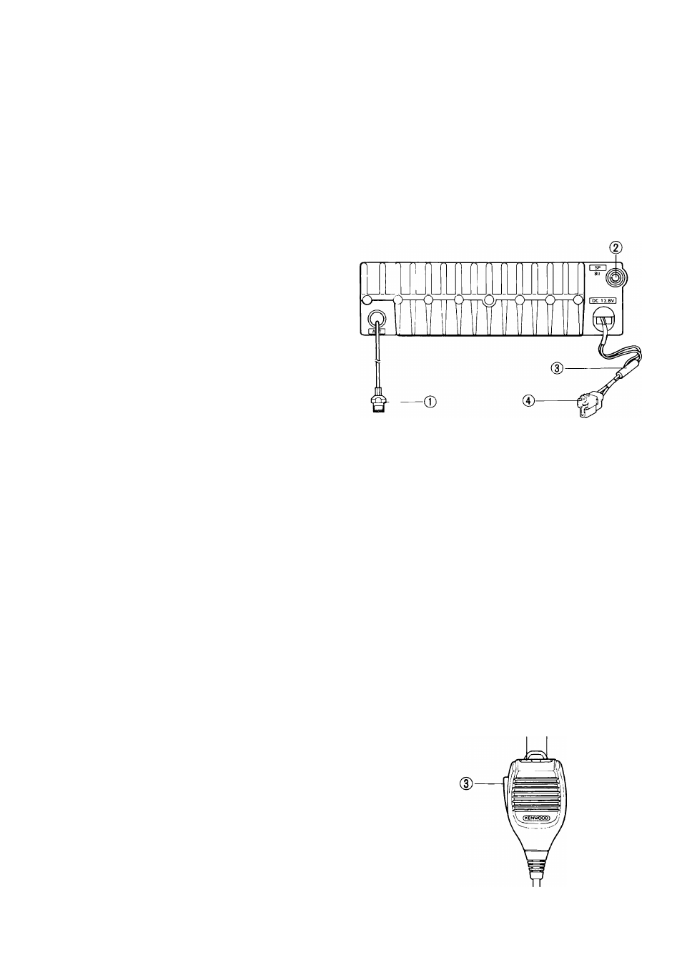
4-1-2. Rear Panel
0
ANT (Antenna) connector
Attach an antenna with an impedance of 50 ohms to
this connector.
0 SP (Speaker) jack
This jack is for connection of an 8-ohm external
speaker.
(3) Fuse holder
Contains one of the following fuses:
TM-221/421 series
: 10A
TM-321A and TM-521 series
: 8A
0
13.8 VDC power input connector
Connect the supplied DC Power Cable to this con
nector. Pay close attention to the polarity (the DC
Power Cable is color-coded; red is positive and black
is negative), when connecting the cable to the power
source.
Qj) BUSY indicator
On whenever the squelch is open.
(0) Frequency display
Displays the transmit/receive frequency, Frequency
Step, or Tone Frequency (TM-221 A/321A/421 A/
521A only).
4-1-3, Microphone
© ®
10