Assembly tip – Kenmore 141.15227 User Manual
Page 12
Attention! The text in this document has been recognized automatically. To view the original document, you can use the "Original mode".
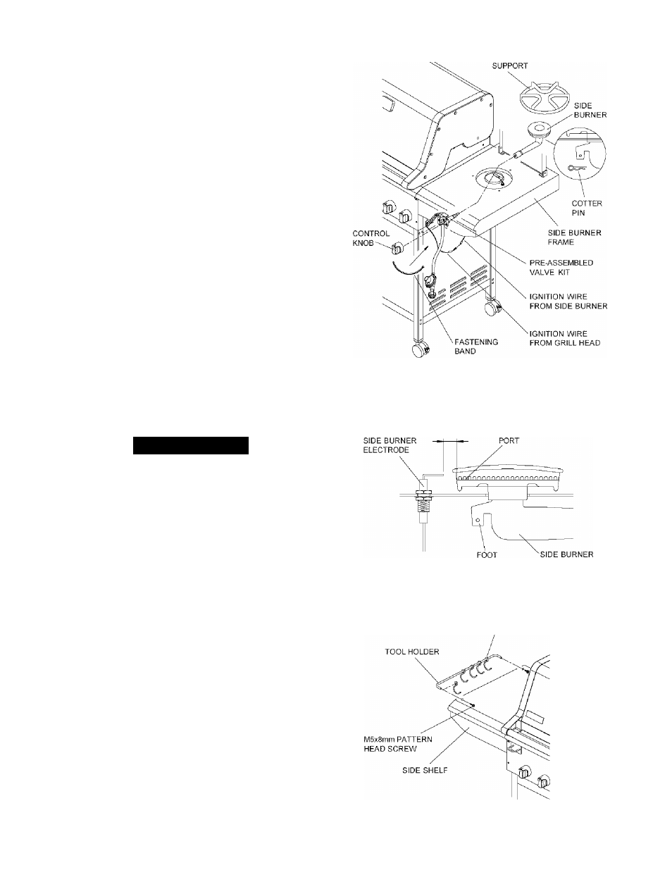
end of Side Burner Tube goes over tip of Side
Burner Valve. Secure Side Burner with supplied
Cotter Pin (packed in Side Burner Control Knob
bag) See Fig. 9b. Place Pot Support into position
on Side Burner Frame.
4. Install the Control Knob to the Side Burner Valve
Stem. See Fig. 9b.
5. Connect the Ignition Wire terminal from Side Burner
with the other from Grill Head, See Fig. 9b. Bind
the connected Ignition Wires and Connection Tube
together using the supplied Fastening Band.
6. The gap between the Side Burner Electrode Tip and
the Side Burner Port should be approximately
1/8"~3/16". See Fig. 9c,
7. If the gap is wider than 3/16", use a pair of long
nose pliers and gently bend the Electrode Tip
toward the Burner.
8. Place the Pot Support into the Side Burner Frame.
See Fig. 9b.
9. Slide the 5 Tool Hooks onto the Tool Holder with
hooks facing the grill Head. Attach Tool Holder to
left side of Side Shelf and secure firmly using 2
of the MbxSrnm Pattern Head Screws supplied. See
Fig. 9d
Figure 9b
POT
Figure 9c
Assembly Tip
When you have finished assembling your Grill
be sure all Pattern Head Thumb Screws
are tightened. You may use the supplied
Tightening Tool (P55IVI3A) as needed.
1
/
8
"~
3
/
16
"
BURNER
Figure 9d
TOOL HOOK
12