Connect the short telephone line cord, 7 mount the telephone to the wall plate, Connect the coiled cord – GE 29831 User Manual
Page 16: Plug in the power supply, Installation - wall mount
Attention! The text in this document has been recognized automatically. To view the original document, you can use the "Original mode".
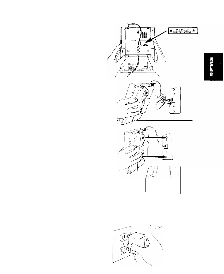
INSTALLATION - WALL MOUNT
5.
Install the Base Plate so that the Arrows Face
Upward
Position the
POWER CORD
in the top and
bottom notches in the
BASE PLATE.
Snap the
base plate into the lower set of tab openings in
the base of the telephone.
6.
Connect the Short Telephone Line Cord
Plug either end of the
SHORT TELEPHONE
LINE CORD
into the
PHONE LINE JACK on
the
back of the telephone. Connect the other end to
the wall phone jack.
7
Mount the Telephone to the Wall Plate
Position the telephone against the wall jack plate
so that pins of the plate align with key hole slots
on the
BASE PLATE.
Press the telephone
against the jack plate so that pins pass through
key hole slots in the
BASE PLATE.
Gently guide
the telephone downward to secure the telephone
to the jack plate.
Note: Be certain that the
AC POWER
CORD and
the
TELEPHONE LINE CORD
stay clear of the
pins of the wall plate and the keyhole slots on the
BASE PLATE.
8.
Connect the Coiled Cord
Plug one end of the coiled cord to the handset
and plug the other into the handset jack. Place
the handset in the cradle.
, !
—
\ ■
O
■ o
■
i
CD O■D
\ .¿) 'J
i)
\ .D
i'
’J
9.
Plug in the Power Supply
Plug the Power Supply into the 110 V AC
power outlet. A tone signal will be heard and
the
MESSAGES INDICATOR
will read “00”.
Lift the
HANDSET
to check for dial tone. The
LINE IN USE
indicator will turn RED. Your
installation is complete.
13