Carl Goldberg GBGA1041 User Manual
Page 9
9
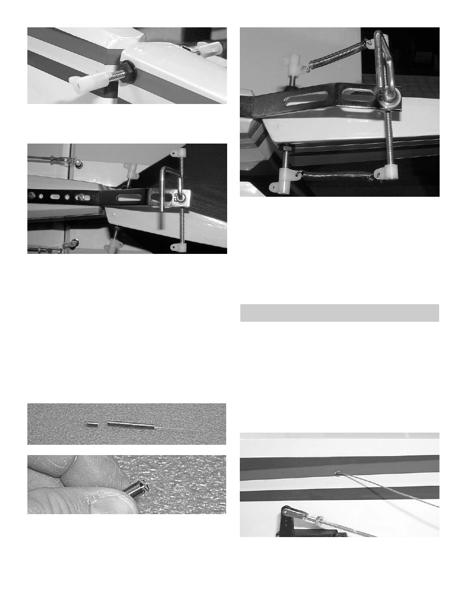
5.
Thread the 2 white adjustable horn brackets
on the rod.
Do this on both sides of the bolt.
6.
Thread the 6-32 x 3” threaded rod half way
into the brass nob that is on top of the axle on
the tailwheel bracket.
Place on the each end of the threaded rod a
white horn bracket.
Mark the center of the fuselage and place the
tail wheel bracket on the center line.
Place the first bend of the bracket where it
bends away from the fuselage just in front of
the rudder hinge line.
7.
Drill a 3/32“ hole in the first and last mounting
holes in the bracket
Mount the tailwheel bracket using 2 #6 x 1/2”
sheet metal screws.
8.
Remove from the tailwheel springs approxi-
mately 1/2” from the other side of the long
wire.
On the side of the spring that you just cut off,
bend 2 or 3 coils of the spring out so that they
can hook through the horn bracket.
9.
Twist the end of the spring on to the horn
bracket. Insert the long wire end around the
second horn bracket. Twist the wire so that it
will stay hooked to the bracket.
10.
Repeat steps 8 & 9.
Note: The springs do not have to be tight to work.
The wheel will pivot easily when ground
taxing.
Install the tailwheel using the 1/8” wheel col-
lars and set screws.
RUDDER SERVO
1.
Collect the following items:
(1) Servo
(1) Cable
(2) Brass Tubes 1/16 OD x 1/4”
(2) 4-40 Rigging Coupler
(2) 4-40 Golden Clevis
(2) 4-40 Hex Nut
2.
Cut the rudder cable in half.
3.
Insert the cable into the hole found just above
the elevator servo.
Repeat for the other side cable.