Carl Goldberg GBGA1041 User Manual
Page 14
14
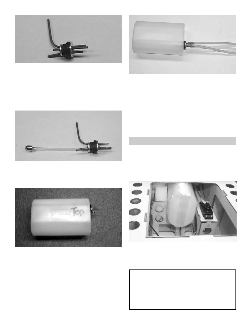
2.
Insert the brass tubes through three of the
holes. They should be arranged so as the long
one will be on the right side of the plane and
the short one on the left side.
The tubes should extend out the front of the
cap 5/8”. Bend the long tube up at about a 20
degree angle. This should be adjusted so the
end of the tube almost touches the top of the
tank when installed.
3.
Install the 4mm silicone tube to the short
brass tube and install the clunk to the other
end of the silicone tube. This is the fuel pick-
up and must be free to “flop” around in the
tank so it can pick up fuel in any attitude.
4.
Install the assembly into the tank so the vent
tube is turned up to the top of the tank and is
positioned on the right side of the tank.
Tighten the screw to expand the rubber cap.
Don’t over tighten or you could split the tank.
5. Attach the three pieces of 5mm tubing to the
three tank outlets. They are different colors so
you can tell which are the two vents and which
is the fuel pickup after the tank is installed.
Make a note of which color you attach to
which tube. The short brass with the clunk is
the fuel pickup and must go to the carburetor.
One of the long brass tubes is the vent and
should go to the pressure outlet on the muffler.
The second vent can be used for filling the
fuel tank but will have to be plugged with a
screw (Not Included) so that the fuel will not
run out.
INSTALLING THE FUEL TANK
1.
Collect the following items:
(1) Fuel Tank
(1) Fuel Line
(4) #2 x 5/16 phillips Head Screw
(1) Wood Hatch Cover
2.
Install the fuel tank into the fuselage.
Place some foam around the fuel tank (foam
not included).
Note:
If you are using a engine that needs to pressur-
ize the fuel system then wrap the fuel tank in
string reinforcing tape to prevent splitting when
under pressure.
The tank provided is for glow fuel only.