Carl Goldberg GBGA1041 User Manual
Page 5
5
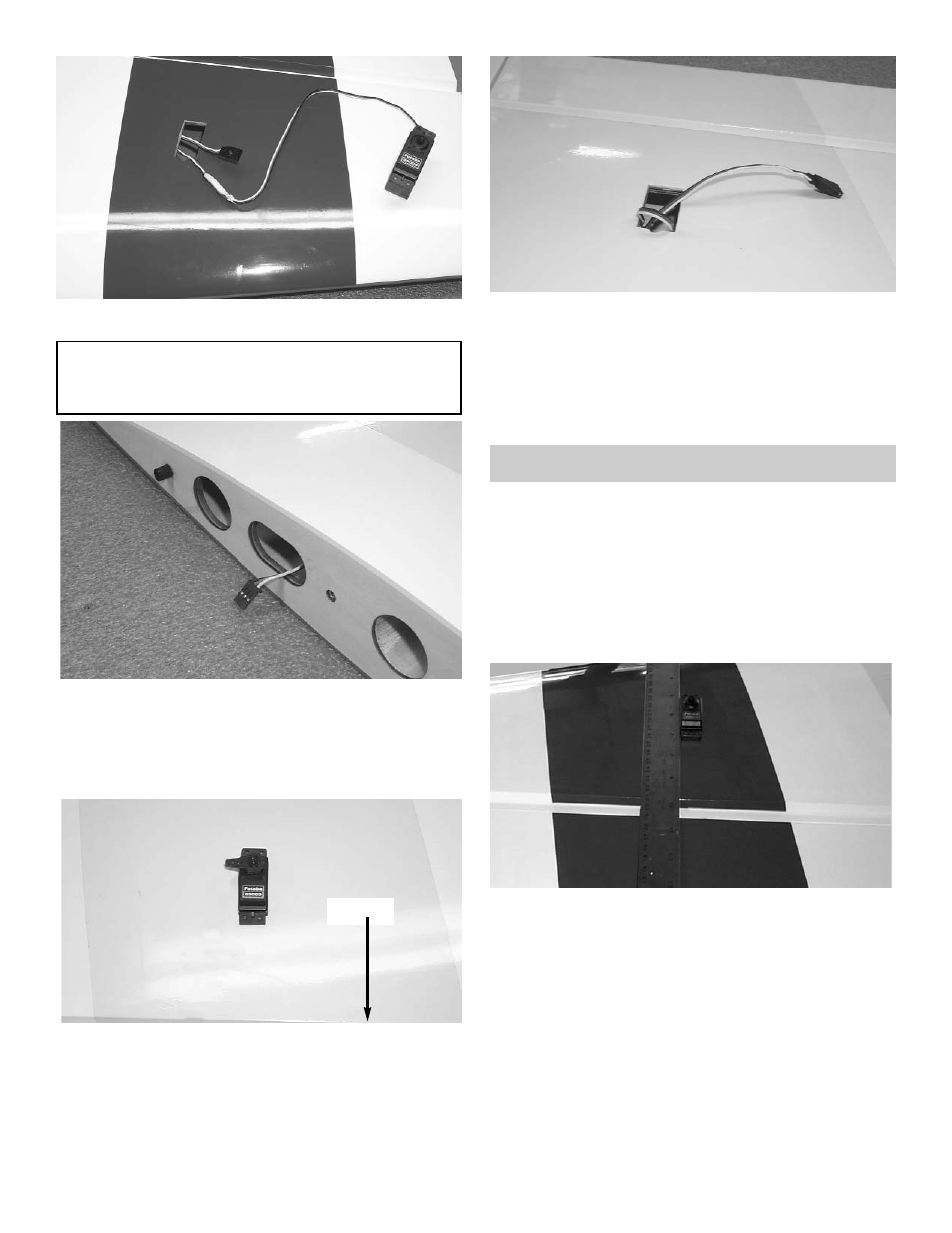
3.
Attach the 24” “Y” harness to one of the servos.
IMPO
RTANT! To ensure that any connections locat-
ed inside the wing will not come loose, either when
the wires are pulled, or during flying, always tape
them securely together with electrical tape.
4.
Starting from the outer servo hole, insert
the “Y” harness and the servo wire into the
servo hole.
Allow the wire to fall straight down through
though the wing till it exits the root rib
.
5.
Tape the end of the plug to the root rib
.
Mount the outer aileron servo to the wing
.
Aileron
6.
Pull the second half of the “Y” harness out
the inner servo hole.
Plug the second aileron servo into the wire
harness.
Always tape them securely
together with electrical tape.
Install the second aileron servo into the wing.
AILERON CONTROL HORN INSTALLATION
2.
With the aileron servo in place, make a mark
on the aileron at a 90º degree angle to the
trailing edge and in line with the servo.
1.
Collect the following items
(8) 4-40 Metal Clevis
(8) 4-40 Hex Nut
(4) 4-40 x 3-3/4" Double Threaded Wire
(4) 6-32 x 2” Bolt
(4) 6-32 Hex Nut
(4) #6 Washer
(4) 6-32 Adjustable Horn Bracket
(4) Clevis Clips