Carl Goldberg GBGA1041 User Manual
Page 8
8
2.
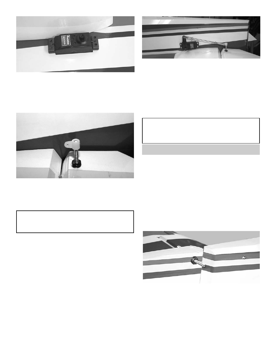
Plug the 24” extensions into the elevator ser-
vos.
Make sure that the extensions plugs are taped
to the servos.
3.
Screw the elevator servos into the fuselage.
4.
Position the control horn bolt so that it is 1/2”
back from the hinge line and 3/4” from the end
of the elevator.
5.
Using a 9/64" drill bit, make a hole in the ele-
vator through to the top side.
6.
Insert the 6-32 x 2” screw from the top through
the elevator.
Place the #6 washer and the 6-32 hex nut on
the bolt and tighten. Make sure that you use
thread lock on the bolt and nut.
Screw the adjustable horn bracket on to the
bolt.
6.
Thread on to each end of the 4-40 x 3-1/2”
pushrod a hex nut and a metal clevis.
Install the metal clevis onto the horn bracket
and the servo arm. tighten the hex nut against
the metal clevis.
Install a clevis clip on to each clevis.
Repeat the above steps for the second eleva-
tor.
HINT: Drill the hole from the bottom half way.
Then measure and mark the top of the
aileron and drill down to the hole from the
top of the aileron.
Caution:
Make sure each metal clevis is fully closed and
a clip is installed before and after each flight.
RUDDER & TAILWHEEL
1.
Collect the following items:
(1) 6-32 x 3” All threaded rod
(4) Small White Adjustable Horn
(2) 6-32 Hex Nut
(2) #6 Flat Washer
(1) Rudder
(3) Hinges
2.
Install the hinges into the rudder and glue the
rudder in place using the same hinging
method used for the elevator and ailerons.
3.
Position the control horn bolt so that it is 1/2”
back from hinge line and 1/2” up from the bot-
tom of the rudder.
Using a 9/64" drill bit, make a hole in the rud-
der.
4.
Center the 6-32 x 3” threaded rod in the hole.
Using thread lock place first the #6 washer
then the 6-32 Hex nut on each side of the rud-
der.