5300i_10_11_12.pdf, Wiring diagrams, Conventional systems (single transformer) – Braeburn 5300 2H-2C Installer Manual User Manual
Page 6: Heat pump systems
10
11
12
NOTES:
1. Transformer Common connection not required for battery-only operation
of thermostat.
2. Second Stage Control connections not used for single stage heating or
cooling systems.
3. For millivolt or other 2-wire heating systems, connect 2 wires from heating
control to R and W1.
NOTES:
1. Transformer Common connection not required for battery-only operation
of thermostat.
2. Second Stage Control connections not used for single stage heating or
cooling systems.
3. For units requiring reversing valve to be energized during heating, connect
reversing valve to B terminal.
For units requiring reversing valve to be energized during cooling, connect
reversing valve to O terminal.
4. Required for units with 2 stage heat only.
5. For 2 stage heat units not having a separate Emergency Heat Terminal, add
installer supplied jumper.
NOTES:
1. Transformer Common connection not required for battery-only operation
of thermostat.
2. Second Stage Control connections not used for single stage heating or
cooling systems.
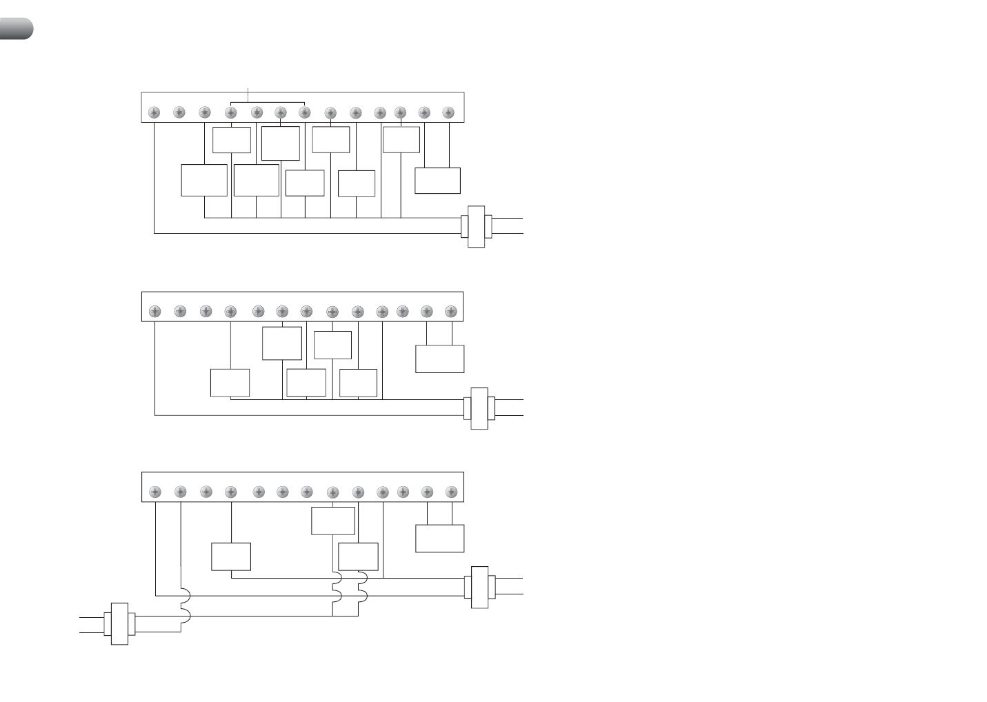
Conventional Systems (Single Transformer)
R
RC
O
W1 / E
B
Y2
W2
Y1
G
C
L
S1
S2
1st Stage
Heat Control
1st Stage
Compressor
Control
2nd Stage
Compressor
Control
(Note 2)
2nd Stage
Heat Control
(Note 2)
Fan Control
Transformer Common (See Note 1)
Remote
Sensor
(Optional)
Neutral
120 VAC
Hot
24 VAC
Heat Pump Systems
R
RC
O
W1 / E
B
Y2
W2
Y1
G
C
L
S1
S2
Emergency
Heat Control
(See note 4)
1st Stage
Compressor
Control
2nd Stage
Compressor
Control
(Note 2)
2nd Stage
Heat Control
(Note 2)
Fan Control
Remote
Sensor
(Optional)
Reversing Valve
(Active in
Cooling-See
Note 3)
System
Malfunction
Indicator
(See Note 5)
Transformer Common (See Note 1)
Neutral
120 VAC
Hot
24 VAC
Reversing Valve
(Active in
Heating-See
Note 3)
Single Stage Conventional Systems (Dual Transformer)
R
RC
O
W1 / E
B
Y2
W2
Y1
G
C
L
S1
S2
1st Stage
Compressor
Control
Transformer Common
(See Note 1)
Cooling
Heating
Fan Control
Neutral
120 VAC
Hot
Neutral
120 VAC
Hot
24 VAC
24 VAC
Remote
Sensor
(Optional)
1st Stage
Heat Control
Wiring Diagrams
6
This model 5300
never requires an
R to RC Jumper.
This model 5300
never requires an
R to RC Jumper.