Setup and adjustments – BASO G196 Series BASOTROL Redundant Combination Gas Valve with Manual Shutoff Valve User Manual
Page 3
G196 Series BASOTROL Redundant Combination Gas Valve with Manual Shutoff Valve Installation Instructions
3
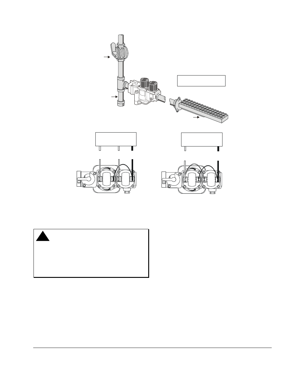
ON
OFF
ON
OFF
Intermittent Pilot
Ignition Control
Main Valve
Connection
Pilot Valve
Connection
Common
Connection
Direct Spark
Ignition Control
Main Valve
Connection
Common
Connection
3 in. (76.2 mm)
Sediment Trap
Shutoff
Valve
X
X indicates possible
locations for other controls.
"A"
G196 Valve
Burner
Figure 2: Typical G196 Gas Valve Installation and Wiring
Setup and Adjustments
Checkout
!
WARNING: Risk of Explosion or Fire.
Follow this or an equivalent checkout procedure
after installation. Before leaving the installation,
verify that the gas valve functions properly and that
the system has no gas leaks. Gas leaks can lead to
an explosion or fire, and may result in severe
personal injury or death.
Make sure all components are functioning properly by
performing the following test.
1.
Test all joints and connections for leaks with a
soap solution.
2.
Close the main upstream shutoff valve and wait
at least 5 minutes for unburned gas to escape
from the appliance, and then reopen the valves.
3.
Turn on the main electrical power switch and
close the thermostat contacts. The appliance
should operate in accordance with the
manufacturer’s specified sequence of operation.
4.
Turn the thermostat to a low dial setting to open
the contacts. All burner flames should be
extinguished. Repeat Steps 3 and 4 at least three
times.
5.
Return the thermostat to a normal setting before
leaving the installation.