BASO G196 Series BASOTROL Redundant Combination Gas Valve with Manual Shutoff Valve User Manual
Page 2
2
G196 Series BASOTROL Redundant Combination Gas Valve with Manual Shutoff Valve Installation Instructions
IMPORTANT:
Do not use a wrench on any
surface other than the casting flats provided at the
inlet and outlet ends of the valve body. The G196
may be damaged in the mounting process if a
wrench is used on any other surface. Using a
wrench incorrectly may void the warranty.
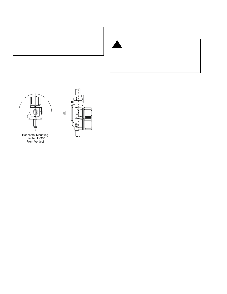
6.
Mount the G196 on a horizontal manifold with the
magnetic operator pointed up (vertical) or in a
position not exceeding 90
° from vertical. The
valve may also be mounted on a vertical manifold
in any position around its axis (Figure 1).
Vertical mounting may be
360 around its axis with
the flow either up or
down, but always in the
direction of the arrow.
90
90
O
O
O
Figure 1: G196 Mounting Positions
7.
Mount the valve to the pipework. Use an
approved pipe joint sealing compound on the
male threads before assembly. Remove excess
compound after mounting the valve to the
pipework. Threads of the pipe and nipples must
be smooth and free of tears and burrs. Steam
clean all piping to remove foreign substances
such as cutting oil or thread chips. Install a
sediment trap in accordance with the National
Fuel Gas Code (ANSI Z223.1).
8.
Attach the pilot gas line to the pilot burner fitting
and to the pilot gas outlet of the valve (if used).
!
WARNING: Risk of Explosion or Fire.
Verify that there are no gas leaks by testing with
appropriate equipment. Never use a match or lighter
to test for the presence of gas. Failure to test
properly can lead to an explosion or fire and may
result in severe personal injury or death.
9.
Check for leakage.
a. Shut off the gas at the main manual shutoff
valve and open the pressure connection
between the manual shutoff valve and the
G196 valve.
b. Connect air tubing with a maximum pressure
of 1-1/2 times the valve’s maximum operating
pressure (as indicated on the valve) to the
opened pressure connection.
c. Paint all valve body connections with a rich
soap and water solution.
If bubbles occur, this is an indication of a leak.
To stop a leak, tighten joints and connections.
Replace the part if the leak cannot be stopped.
If bubbles do not occur, remove the air tubing
and close the pressure connection.
10. Perform
the
Checkout section before leaving the
installation.