Wiring – BASO BGAH96 Series BASOTROL User Manual
Page 3
BASOTROL CE Approved Class B Shutoff Gas Valve Installation Instructions 3
Wiring
!
WARNING:
Risk of Shock.
Disconnect the power supply before making
electrical connections to avoid electrical shock or
equipment damage. Ensure that the operating
voltage is identical to the information on the product
identification label.
!
CAUTION:
Risk of Equipment Damage.
For 12 VDC, 25 VDC and 25 VAC applications, the
ground wire must not be connected to prevent
possible grounding of the 12 VDC or 25 VDC power
supply or 25 VAC transformer secondary.
The BGA171/H96 valve is supplied with 3-tab and
2-tab electrical connections. The tabs of the solenoid
coil are male tag terminals, and electrical connections
should be made using 1/4 in. (6.35 x 0.8 mm) female,
fully insulated push-on terminals. The earth ground
terminal is clearly labeled with the earth ground
symbol (see Figure 2).
Note: Electrical connections can also be made using
pre-wired electrical plugs (DIN 43650 [ISO 4400]).
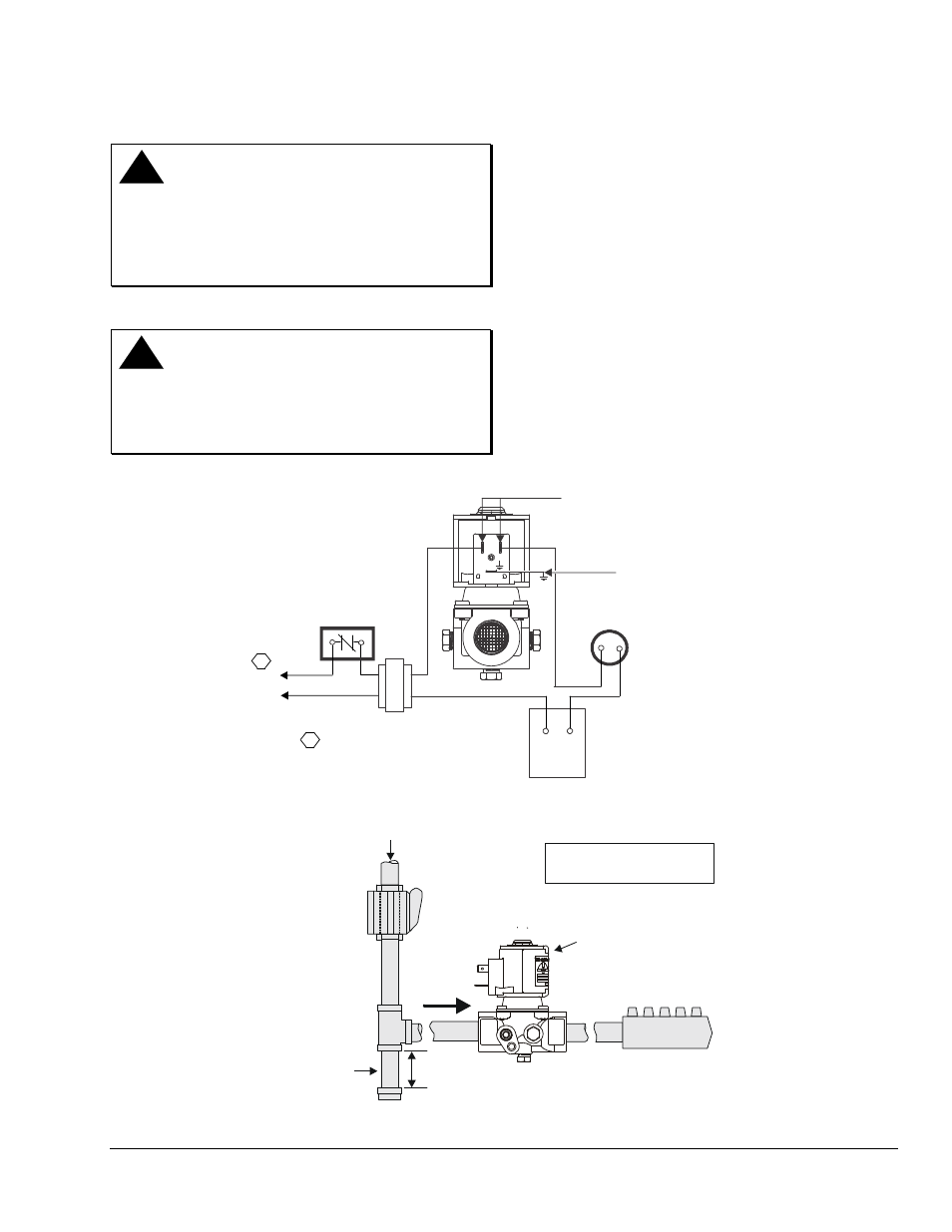
Non-Polarity Sensitive
Connections
Ground Tab
25 VDC, 25V, 120V and 240V Only
1
L1 (Hot)
L2 (Neu)
1
Power supply provides disconnect
means and overload protection
as required.
Safety
Control
24 Volt
Thermostat
Limit(s)
Figure 2: Electrical Connections
X
indicates possible
locations for other controls.
Gas Flow
Shutoff Valve
BGA171/H96
Gas Valve
X
X
Sediment
Trap
3 in. (76.2 mm)
Minimum
Burner
Direction
of Flow
PRESS
TAP
OUT
IN
Figure 3: Typical BGA171/H96 Installation