BASO BGQ15HAA-1 User Manual
Page 2
2 BGQ15HAA-1 Retrofit Spark Ignition System Installation Instructions
Install the Sensing Probe and Cable
To install the sensing probe and cable:
1.
Remove the thermocouple from the existing pilot
burner. The pilot burner should be left on its
mounting bracket if you can conveniently reach it.
If not, it may be necessary to partially pull out the
manifold for easy access. In some extreme
cases, it may be necessary to remove the pilot. If
it becomes necessary to replace the pilot burner,
it must be replaced with an identical model and
positioned using the original mounting.
2.
Place the threaded end of the sensing probe
assembly into the thermocouple hole in the pilot.
3.
Check the position of the spark gap. The spark
gap should be 0.1 in. (2.5 mm) nominal.
Note: Position the spark gap in the pilot gas
stream. Raise or lower the spark gap by adding
or removing the spacers provided between the
pilot and sensing probe assembly.
4.
Screw the cone shaped nut onto the probe. The
small end fits into the threaded thermocouple
hole to center the sensing probe and secure it in
place.
5.
Depending upon the appliance, the flame sensing
probe may be mounted in a number of positions.
Select the position providing the most clearance
from metal surfaces and the main burner flame.
6.
Install the sensing probe cable onto the spade
connector of the sensor.
7.
If the pilot burner was removed, reinstall the pilot
on its bracket in the furnace using the original
mounting.
Mounting
IMPORTANT:
Verify that the valve is installed
only in applications where the specified maximum
ambient (surface) temperature and maximum
operating pressures do not exceed the limits in the
Technical Specifications section.
To install the BGQ15HAA-1 ignition system:
1.
Compare the voltage on the valve with the power
source voltage to ensure the correct unit is being
installed. For valves with 25 volt coils, use an
NEC, Class 2 transformer.
Note: The transformer must be mounted to a
grounded metal enclosure.
2.
When installing the ignition system on the
manifold, ensure that the gas flows through the
valve body in the direction indicated by the arrow
on the valve body. If the ignition system is
installed with the gas flow in the opposite
direction of the arrow, leakage can occur.
IMPORTANT:
Do not use a wrench on any
surface other than the casting flats provided at the
inlet and outlet ends of the valve body. The
BGQ15HAA-1 may be damaged in the mounting
process if a wrench is used on any other surface.
Using a wrench incorrectly may void the warranty.
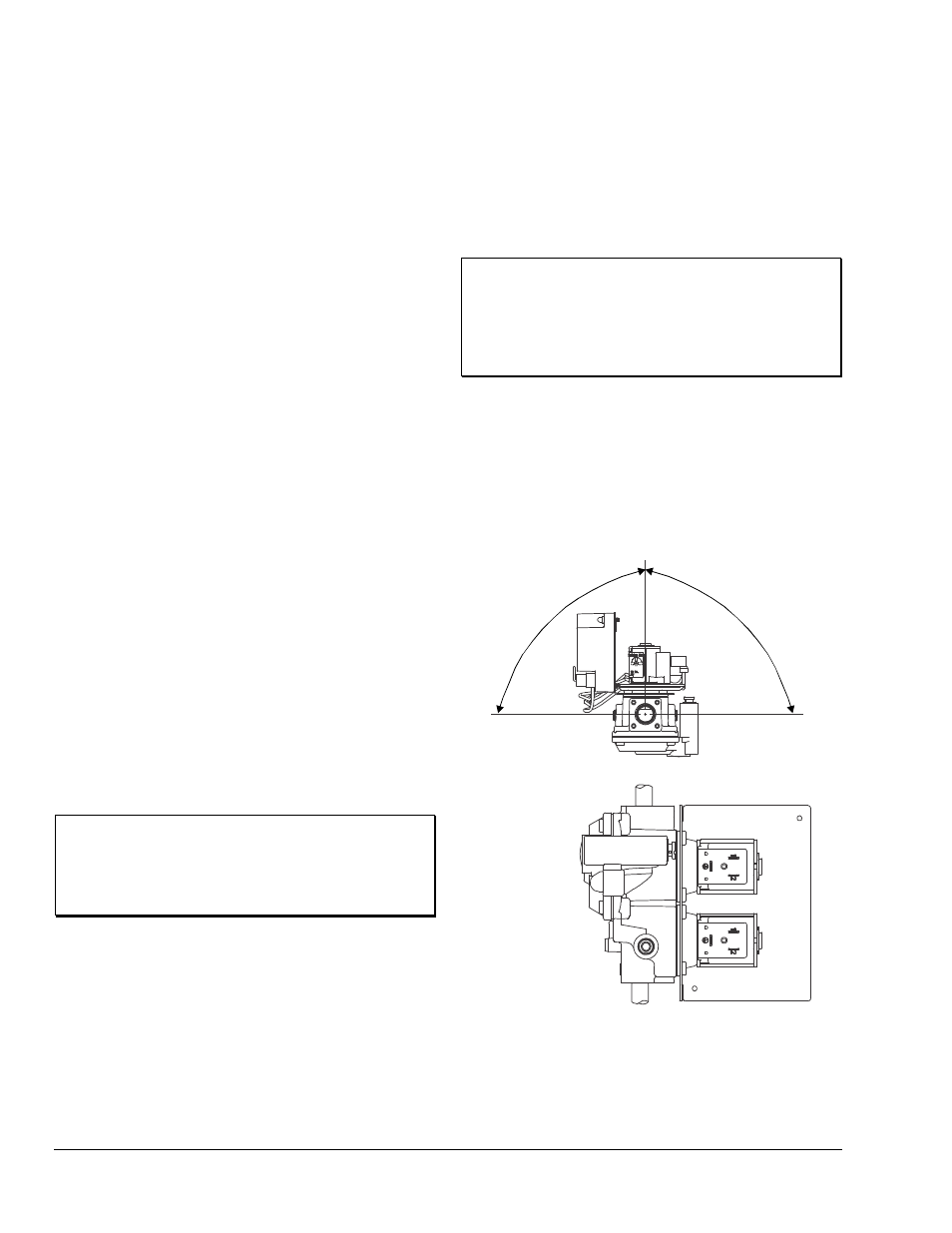
3.
Mount the BGQ15HAA-1 ignition system on a
horizontal manifold with the ignition control
pointed up (vertical) or in a position not
exceeding 90
° from vertical manifold in any
position around its axis (Figure 1).
Note: Additional piping may be required if
face-to-face dimensions are not the same.
90° Maximum
from Vertical
Vertical mounting may
be 360º around its axis
with the gas flow either
up or down, but always in
the direction of the arrow.
90° Maximum
from Vertical
Figure 1: BGQ15HAA-1 Mounting Positions