BASO BG1600M51EF-1AA User Manual
Page 8
8 BG1600M51EF-1AA Universal Intermittent Pilot Ignition Control Installation Instructions
1
2
3
4
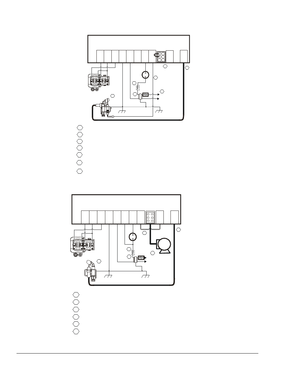
Power Supply. Provides disconnect means and overload protection as required.
Maximum cable length 48 inches (1,220 mm). (Resistive wire recommended.)
Alternate location for limit controller.
Controls in 24V circuit must not be in ground leg to transformer.
MV/PV
(COM)
PV
GN
D
BU
R
N
ER
GND
24V
SENSE
SPARK
Thermostat
High
Temp
Limit
Pilot
Burner/Ignitor
Flame
Sensor
24VAC
Class 2
Transformer
IN
T
E
R
N
A
L
2
3
4
5
6
8
9
10
1
2
4
5
L1 (Hot)
L2 (Neu)
6
Combination
Gas Valve
TH
7
MV
5
Maximum cable length 48 inches (1,220 mm).
1
Chassis or Frame
Ground
6
Sensor rod must be 3/8” (9.53 mm) to 1/2” (12.7 mm) of the sensor tip should
be in the flame for proper sensing signal.
Use jumper
plug supplied
with control.
3
7
For two rod application, remove jumper wire before installation.
Discard
Sense Jumper
7
Figure 3: Wiring for 2 Rod Flame Sense with Vent Damper Jumper Plug
MV
MV/PV
(COM)
PV
GN
D
B
U
RNE
R
GND
24V
TH
SENSE
IN
T
E
RNA
L
SPARK
Thermostat
High
Temp
Limit
DA
M
P
E
R
PL
U
G
Vent
Damper
Wiring
Harness
Pilot
Burner/Ignitor
Combination
Gas Valve
Jumper
24VAC
Class 2
Transformer
Discard jumper
plug supplied
with the control.
1
2
3
5
4
Power Supply. Provides disconnect means and overload protection as required.
Maximum cable length 48 inches (1,220 mm). (Resistive wire recommended.)
For single rod application, leave jumper wire in as received.
Alternate location for limit controller.
Controls in 24V circuit must not be in ground leg to transformer.
1
2
3
4
5
6
7
8
9
10
L1 (Hot)
L2 (Neu)
1
2
3
4
5
6
Chassis or Frame
Ground
Sensor rod must be 3/8” (9.53 mm) to 1/2” (12.7 mm) of the sensor tip should
be in the flame for proper sensing signal.
6
Figure 4: Wiring for 1 Rod Flame Sense with Vent Damper