BASO BG1600M 2010 User Manual
Page 3
BG1600M Intermittent Pilot Ignition Control with Rollout Switch Installation Instructions 3
Power Supply. Provides disconnect means and overload protection as required.
GN
D
(M
V
/PV)
GN
D
(B
UR
NE
R)
PV
24V
/T
H
SEN
SE
SP
AR
K
IN
T
E
R
N
2
3
4
5
6
8
9
10
MV
7
1
1
2
3
4
Maximum cable length 48 inches (1,220 mm). (Resistive wire recommended.)
Alternate location for limit controller.
Controls in 24V circuit must not be in ground leg to transformer.
Thermostat
High
Temp
Limit
24VAC
Class 2
Transformer
1
2
3
4
L1 (Hot)
L2 (Neu)
5
Combination
Gas Valve
5
Maximum cable length 48 inches (1,220 mm).
Chassis or Frame
Ground
6
Sensor rod must be 3/8” (9.53 mm) to 1/2” (12.7 mm) of the sensor tip should
be in the flame for proper sensing signal.
Pilot
Burner/Ignitor
Flame
Sensor
6
GN
D
(2
4
V
)
R.O
. S
W
Rollout
Switch
PV
MV
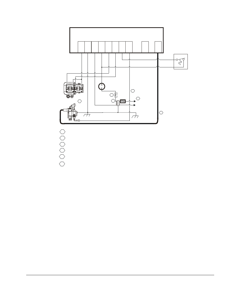
Figure 1: Wiring for 2 Rod Flame Sense with Rollout Switch
Rollout Switch Function
The rollout switch is wired to the BG1600M ignition control
at Terminal 7 (R.O. SW) and Terminal 4 (24V/TH) (see
Figure 1). The rollout switch (a normally closed set of
contacts) is positioned to detect flames rolling out of the
combustion chamber. If rollout occurs, the switch contacts
open and the BG1600M immediately goes into a lockout
condition, closing the main and pilot valves so that the
system is not allowed to function.
The thermostat contacts must be opened for 30 seconds,
then closed to escape the lockout condition. When the
rollout switch contacts have returned to the closed
position, the BG1600M will start its operating sequence
when the thermostat contacts close.