Figure 1: wiring for 1 rod flame sense, Figure 2: wiring for 2 rod flame sense – BASO BG1100M User Manual
Page 3
BG1100M Direct Spark Ignition Control Installation Instructions 3
VA
L
V
E
(C
O
M
)
VA
L
V
E
GN
D
B
URNE
R
GND
24V
SENSE
SPARK
Chassis or Frame
Ground
Thermostat
High
Temp
Limit
Burner/ignitor
24VAC
Class 2
Transformer
2
3
4
5
6
8
10
L1 (Hot)
L2 (Neu)
1
2
3
4
1
2
3
4
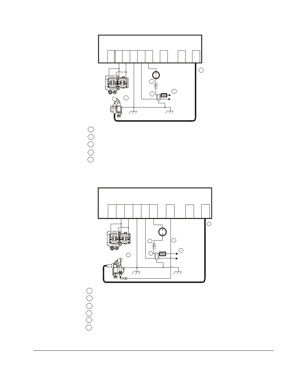
Power Supply. Provides disconnect means and overload protection as required.
Maximum cable length 48 inches (1,220 mm). (Resistive wire recommended.)
Alternate location for limit controller.
Controls in 24V circuit must not be in ground leg to transformer.
Combination
Gas Valve
5
5
Sensor rod must be 3/8” (9.53 mm) to 1/2” (12.7 mm) of the sensor tip should
be in the flame for proper sensing signal.
Figure 1: Wiring for 1 Rod Flame Sense
1
2
3
4
Power Supply. Provides disconnect means and overload protection as required.
Maximum cable length 48 inches (1,220 mm). (Resistive wire recommended.)
Alternate location for limit controller.
Controls in 24V circuit must not be in ground leg to transformer.
VA
L
V
E
(C
OM
)
VA
LV
E
GN
D
BU
R
N
ER
GND
24V
SENSE
SPARK
Thermostat
High
Temp
Limit
Burner/Ignitor
Flame
Sensor
24VAC
Class 2
Transformer
2
3
4
5
6
8
10
1
2
3
4
L1 (Hot)
L2 (Neu)
5
Combination
Gas Valve
5
Maximum cable length 48 inches (1,220 mm).
Chassis or Frame
Ground
6
6
Sensor rod must be 3/8” (9.53 mm) to 1/2” (12.7 mm) of the sensor tip should
be in the flame for proper sensing signal.
Figure 2: Wiring for 2 Rod Flame Sense