Neptronic, Linkage assembly replacement – AERCO Electronic Control Valve User Manual
Page 37
VA-115 INSTRUCTIONS – ELECTRONIC CONTROL VALVE, CXT-E
8-13
0
90
neptronic
1 2 3
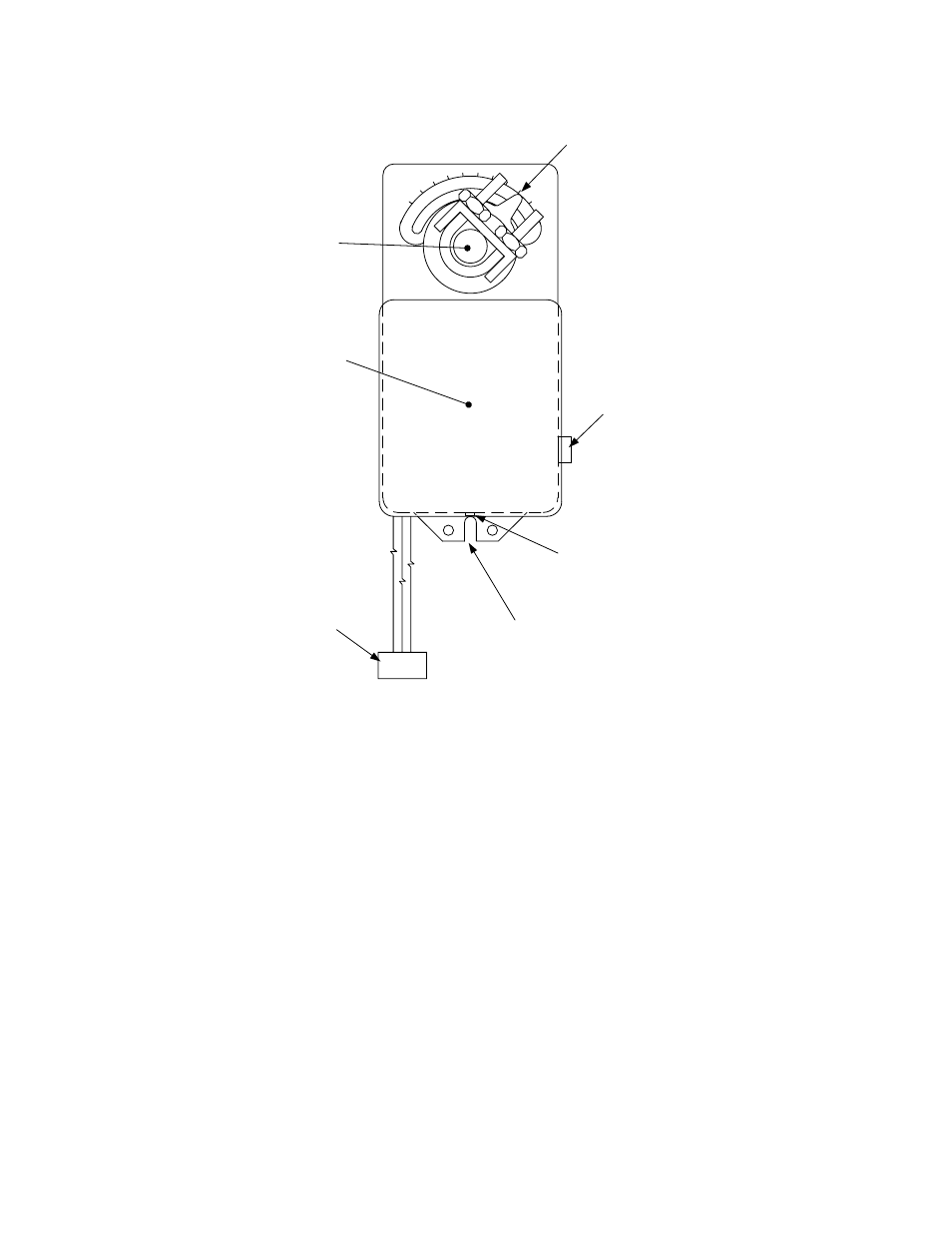
COVER
SET SCREW
CLUTCH
DIAL &
POINTER
CENTER
SLOT
COVER
CABLE
CONNECTOR
LINKAGE
SHAFT
Figure 8-5. Actuator Replacement
LINKAGE ASSEMBLY REPLACEMENT
As Figure 8-6 shows, the Linkage Assembly Part No. will vary, depending on valve size. CXT-E valve
sizes from 1.00 to 3.00 inches utilize Linkage Assembly Part No. 24038-1. However, 4.00 inch CXT-E
Valves utilize Linkage Assembly Part No. 24038-2. The primary difference between the 24038-1 and
24038-2 Linkage Assemblies is the Adapter shown in Figure 8-6. In addition, the Linkage Pin location for
the 24038-1 assembly will vary for 1.00 to 2.00 inch valves and for 2.50 to 3.00 inch valves. IT IS
IMPERATIVE THAT THE CORRECT ADAPTER AND PIN LOCATION BE USED FOR THE VALVE SIZE
BEING REPAIRED. The Linkage Assembly is attached to the Control Valve Top with two Cap Screws.
The Linkage Gasket (Part No. 81046) should also be replaced when installing a new Linkage Assembly.
- AERClean (12 pages)
- ProtoNode Gateway Rev 1 (with internal LEDs) (64 pages)
- ProtoNode Gateway Rev 3 (with external LEDs) (126 pages)
- Control System (ACS) (144 pages)
- Belimo F6...HD/HDU Series Valve (44 pages)
- Belimo AF120-S US Actuator (9 pages)
- Belimo AMX24-MFT Actuator (9 pages)
- Belimo GKX24-MFT Actuator (9 pages)
- Belimo Motorized Valves Installation (20 pages)
- BMS II BOILER (108 pages)
- BMS II BOILER MODBUS Communication (100 pages)
- BMS 168 (86 pages)
- Boiler Valve Controller (BVC) PRIOR to Serial-12-840-1 (35 pages)
- Boiler Valve Controller (BVC) (38 pages)
- Buffer Tanks (14 pages)
- Combination Control Panel (CCP) (4 pages)
- XPC GATEWAY Communications (193 pages)
- Domestic Water Storage Tank (19 pages)
- Steam Traps (6 pages)
- X100 – Inhibitor (4 pages)
- AM Series Boiler User Manual (156 pages)
- AM Series Boiler Cascade Sequencer Controller (26 pages)
- AM Series Boiler Modbus Interface Manual (18 pages)
- BMK 1.5 LN October 2012 (166 pages)
- BMK 1.5 LN July 2011 (152 pages)
- BMK 1.5 LN June 2010 (123 pages)
- BMK 1.5 LN May 2009 (111 pages)
- BMK 1.5 LN Dual Fuel Feb 2013 (162 pages)
- BMK 1.5 LN Dual Fuel June 2010 (139 pages)
- BMK 1.5 LN Dual Fuel Jan 2009 (126 pages)
- BMK 1500-2000 (188 pages)
- BMK 1500DF (196 pages)
- C-More Control Panel (162 pages)
- BMK 2.0 LN October 2012 (172 pages)
- BMK 2.0 LN Natural Gas (SN G-11-1861 and above) (170 pages)
- BMK 2.0 LN Nat. Gas June 2010 (125 pages)
- BMK 2.0 LN Natural Gas 2008 (111 pages)
- BMK 2.0 LN Nat. Gas for Mass. only (113 pages)
- BMK 2.0 LN Dual Fuel Serial G-11-2402 and UP (160 pages)
- BMK 2.0 LN Dual Fuel Nov 2010 (139 pages)
- BMK 2.0 LN Nat. Gas (112 pages)
- BMK 2.0 LN for Mass. only (114 pages)
- BMK 3.0 LN Dual-Fuel Series Gas Fired Low NOx Boiler System (136 pages)
- BMK 3.0 LN Natural Gas July 2011 (129 pages)
- BMK 3.0 LN Nat. Gas Jan 2011 (129 pages)