5 - functional description, Introduction, Functional overview – AERCO Electronic Control Valve User Manual
Page 17
VA-115 INSTRUCTIONS – ELECTRONIC CONTROL VALVE, CXT-E
5-1
5 - FUNCTIONAL DESCRIPTION
INTRODUCTION
The AERCO Electronic Control Valves, Type CXT-E are highly responsive devices which precisely
modulate the position of the Valve shaft based on the control signal input. As mentioned in Section 1,
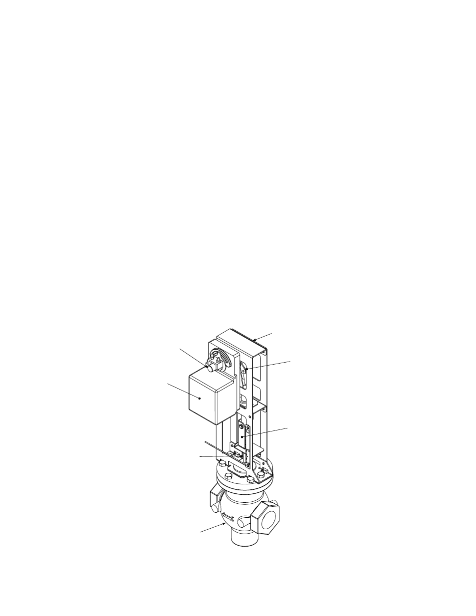
each Control Valve consists of a Valve Body, Linkage Assembly and Actuator. Figure 5-1 illustrates the
three major assemblies of the Control Valve. The following paragraphs provide a brief functional overview
of the Electronic Control Valve, Type CXT-E.
FUNCTIONAL OVERVIEW
All Control Valves, Type CXT-E, regardless of size, utilize identical Actuators (Part No. 69009). The
Actuator is mounted on the upper portion of the Linkage Assembly and is secured to the Linkage shaft
(Figure 5-1). An Adapter is used to secure the Linkage to the Valve Body Shaft. The Valve Actuator is
powered by 24 VDC and is controlled by a linear 4-to-20 mA control signal input from the external
Temperature Controller. A 4 mA control signal corresponds to a fully closed valve position, while a 20 mA
signal corresponds to a fully open position.
As described in Section 3 (Adjustment), the Control Valve Actuator is self-calibrating for all sizes of
AERCO Control Valves. The CXT-E Valve Actuator also incorporates a fail-safe mechanism which
automatically closes the Control Valve in the event of a loss of input power loss or control signal.
LINKAGE
ASSEMBLY
LINKAGE
SHAFT
MECHANICAL
LINKAGE
LINKAGE
ADAPTER
ACTUATOR
VALVE
SHAFT
VALVE
BODY
Figure 5-1. Electronic Control Valve, Type CXT-E