AERCO MXG-461 Series Control Valve - Manufactured by Siemens User Manual
Page 6
6/14
Siemens
Modulating control valves with magnetic actuators, PN16
CA1N4455en
Building Technologies
15.12.2009
The two-color LED display indicating operating status can be viewed by opening the
cover of the electronics module.
LED
Indication
Function
Remarks, troubleshooting
Green Lit
Control mode
Automatic operation; everything o.k.
Flashing
Calibration
In manual control
Wait until calibration is finished
(green or red LED will be lit)
Hand wheel in MANUAL or OFF position
Red Lit
Calibration error
Internal error
Recalibrate (operate button in opening 1x)
Replace electronics module
Flashing
Mains fault
Check mains network (outside the frequency or
voltage range)
Both
Dark
No power supply
Electronics faulty
Check mains network, check wiring
Replace electronics module
As a general rule, the LED can assume only the states shown above (continuously red
or green, flashing red or green, or off).
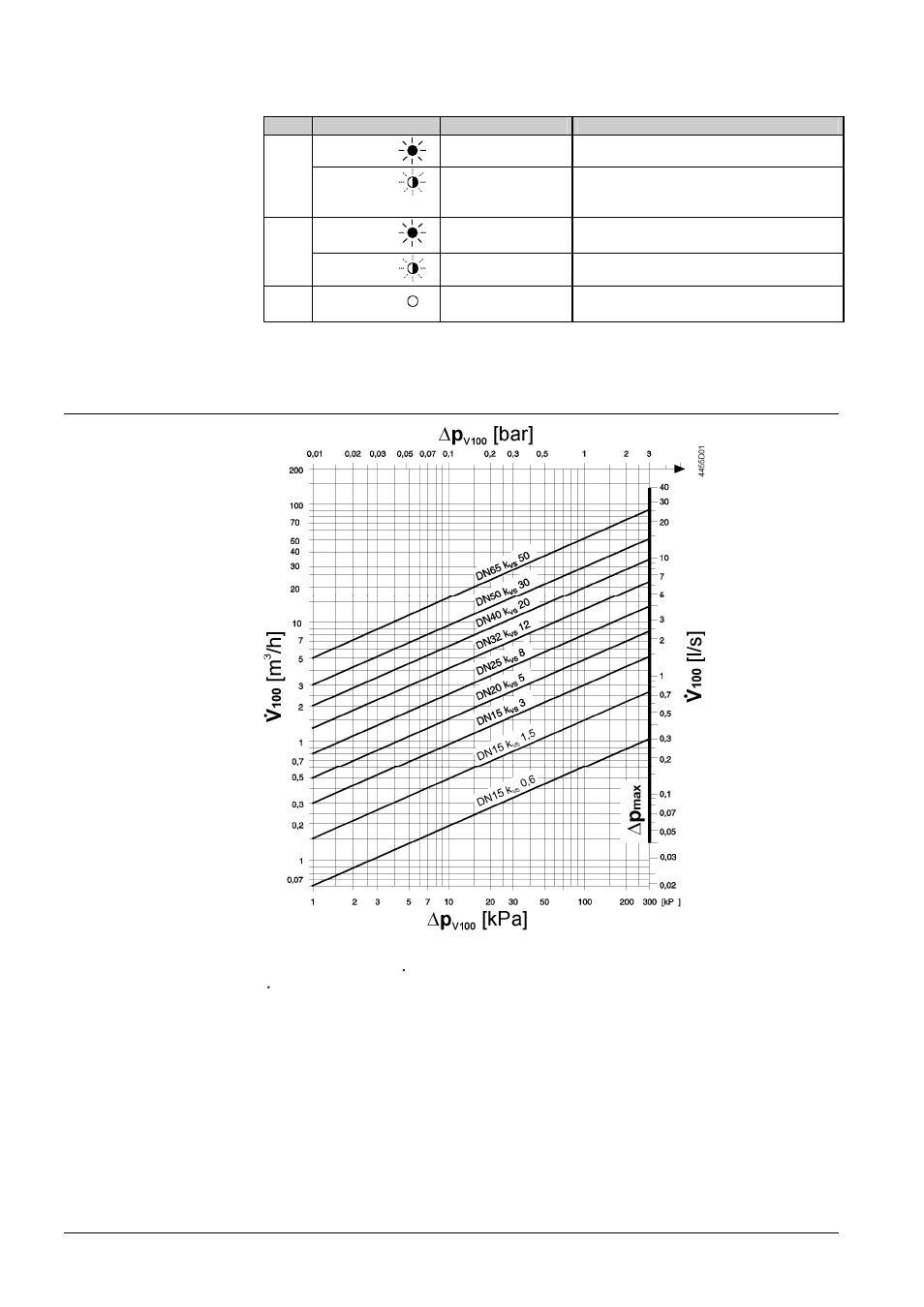
Sizing
Δp
V100
= differential pressure across the fully open valve and the valve’s control path A
→ AB by a
volume flow V
100
V
100
= volume flow through the fully open valve (H
100
)
Δp
max
= max. permissible differential pressure across the valve’s control path for the entire actuating
range of the motorized valve
100 kPa = 1 bar
≈ 10 mWC
1 m
3
/h = 0.278 l/s water at 20 °C
When sizing valves for media other than water, note that the medium properties
• specific
heat
• density
• kinematic
viscosity
differ from water. All variables depend on temperature. The design temperature is the
lowest medium temperature in the valve.
Indication of
operating state
Flow chart
Note for media other
than water