AERCO MXG-461 Series Control Valve - Manufactured by Siemens User Manual
Page 11
11/14
Siemens
Modulating control valves with magnetic actuators, PN16
CA1N4455en
Building Technologies
15.12.2009
General
environmental conditions
Operation
EN 60721-3-3
Transport
EN 60721-3-2
Storage
EN 60721-3-1
MX..461.., MX..461..P Climatic conditions
Class 3K5
Class 2K3
Class 1K3
Temperature
-5...+45 °C
-25...+70 °C
-5...+45 °C
Humidity
5...95 % r.h.
5...95 % r.h.
5...95 % r.h.
Mechanical conditions
EN 60721-3-6
Class 6M2
EN 60721-3-3
EN 60721-2
EN 60721-2
MX..461..P Mechanically active substances
Class 2M2
Class 2M2
Biological requirements
Class 3B2
Chemically active substances
Class 3C1
Mechanically active substances
Class 3M2
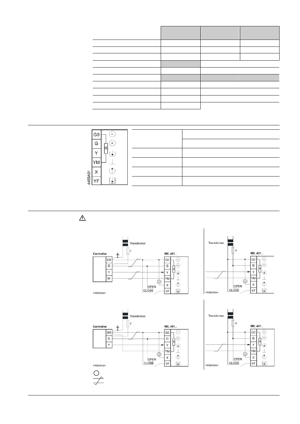
Connection terminals
System neutral
AC 24 V operating
voltage
System potential
Positioning signal
DC 0...10 V / 2...10 V / 4...20 mA
Measuring neutral (= G0)
Position feedback signal
DC 0...10 V
Force control input
R = Inner resistance between G0 and YM, approx 10 kΩ
Connection diagrams
If controller and valve receive their power from separate sources, only one
transformer may be earthed on the secondary side.
Common transformer
Separate transformer
Common transformer
U
Indication of valve position (only if required). DC 0 ...10 V → 0...100 % volumetric flow V
100
Twisted pairs. If the lines for AC 24 V power supply and the DC 0...10 V (DC 2...10 V,
DC 4... 20 mA) positioning signal are routed separately, the AC 24 V line need not be twisted.
Caution
Terminal assignment
for controller with
4-wire connection
(to be preferred!)
Terminal assignment
for controller with
3-wire connection