Installation, Danger – AERCO BMK 2.0 LN Natural Gas 2008 User Manual
Page 16
INSTALLATION
2-6
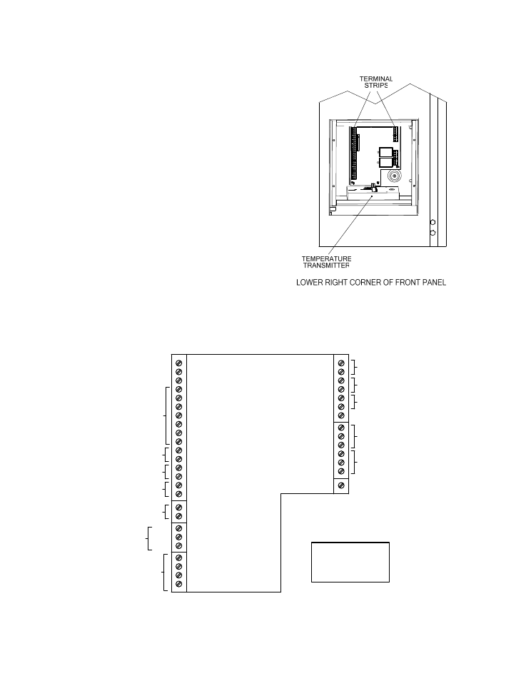
In addition to the terminal strips shown in Figure
2-9, the I/O Box also contains a pre-wired
temperature transmitter which receives inlet air
temperature sensor readings and transmits this
signal to the variable frequency drive (VFD)
contained in the Boiler. The VFD utilizes this
input signal to adjust the rotation speed of the
blower.
Brief descriptions of each mode of operation,
and their wiring requirements, are provided in
the following paragraphs. Additional information
concerning field wiring is provided in paragraphs
2.10.1 through 2.10.10. Refer to Chapter 5 for
detailed information on the available modes of
operation.
2.9.1 Constant Setpoint Mode
The Constant Setpoint Mode is used when it is
desired to have a fixed setpoint that does not
deviate. No wiring connections, other than AC
electrical power connections, are required for
this mode. However, if desired, fault monitoring
or enable/disable interlock wiring can be utilized
(see paragraphs 2.10.9.1 and 2.10.10).
Figure 2-9.
Input/Output (I/O) Box Location
mA OUT
RS-485
COMM.
+
-
+
-
ANALOG IN
SENSOR COMMON
OUTDOOR SENSOR IN
REMOTE INTL'K IN
B.M.S. (PWM) IN
SHIELD
+
-
+
-
AUX SENSOR IN
NOT USED
EXHAUST SWITCH IN
DELAYED INTL'K IN
FAULT RELAY
120 VAC, 5A, RES
AUX RELAY
120 VAC, 5A, RES
G
RELAY CONTACTS:
120 VAC, 30 VDC
5 AMPS RESISTIVE
DANGER
120 VAC USED
IN THIS BOX
NOT USED
NOT USED
NC
COM
NO
NC
COM
NO
NOT USED
Figure 2-10. I/O Box Terminal Strip