Input shaft and bypass rod – Cub Cadet ZD User Manual
Page 26
EZT
®
23
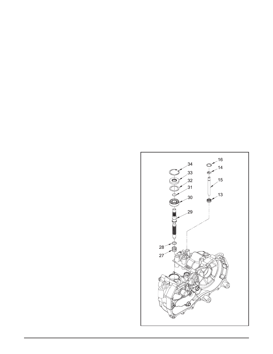
figure 15. input shaft and Bypass rod assembly
Refer to Figure 15.
disassembly
1. Remove the control arm and bypass arm.
See page 16.
2. Drain the oil from the transaxle. See page
9.
3. Remove the side cover. See page 20.
4. Remove the reduction gears. See page
21.
5. Remove the motor shaft. See page 22.
6. Remove the retaining ring (34) and shaft
seal (33). Discard the seal.
7. Remove the spacer (32) and input shaft
assembly (29, 30 & 31).
8. Remove the compression spring (27) and
washer (28).
9. Remove the rings (14 & 16), bypass rod (15)
and seal (13).
inspection
1. Inspect the input shaft components and
bypass rod for wear or damage.
assembly
1. Visually ensure that the pump block is
aligned concentrically with the center sec-
tion running face.
2. Install the compression spring (27) and
washer (28).
3. Insert the input shaft (29), with bearing (30)
and retaining ring (31), into the pump block
assembly. NOTE: Do not force the shaft and
bearing as damage may occur. If alignment
is correct, the shaft assembly will fit into
place.
4. Install the washer (32), seal (33) and retain-
ing ring (34). Use a seal protector when
installing the input shaft seal.
5. Deburr the end of the bypass rod. Install the
bypass rod (15), retaining ring (14), seal (13)
and retaining ring (16).
6. Install the motor shaft. See page 22.
7. Install the reduction gears. See page 21.
8. Install the side cover. See page 20.
9. Install new seals in the side housing. See
page 17.
10. Fill the transaxle with oil. See page 9.
11. Install the bypass arm and control arm. See
page 16.
inpuT sHafT and BYpass rod