Checkline TD-1-TE User Manual
Page 6
-6-
5 .0 O
PERAT I ON
1. Install the sensor at the desired measuring location.
2. Connect the TD-1-TE with the supplied sensor as described Section 8.2..
Only sensors which comply with the specifications given in
Section 8.3 may be connected.
3. Connect the indicator unit with the power supply as described in Section
8.2 If a longer connecting cable should be required to connect the sensor
with the TD-1-TE, note the pin assignment of the sensor's 8-pin connector
indicated in the specifications of the sensor's Operating Instructions.
To avoid random noise and malfunctions, make sure the cable
connecting the TD-1-TE with the sensor is not laid parallel to power
lines or highly loaded signal lines, regardless of the type of voltage.
NOTE:
The requirements of the CIE specification are only complied with
if the TD-1-TE is equipped and operated with sensors and connecting
cables supplied by Electromatic Equipment Company. Certification to the
CIE specification does not extend to, and shall be invalid for any other
combination. Under no circumstances shall Electromatic Equipment
Company be held liable for any resulting damage.
4. Switch on the power to the TD-1-TE. Allow approx. 10 minutes
for thermal stabilization.
5. If the material path is other than vertical or if the process material deviates
significantly from the Electromatic calibration material, you need to carry
a zero and gain adjustment before using, as described in Sections 6.1
and 6.2.
6. Thread the process material through the measuring rollers, following the
red marking on the front of the sensor.
7. The digital display will now show the measured line tension.
WARNING
WARNING
Process Material
Material Path Symbol
-11-
7 .0 A
N ALOG
I
N T ERFACE
The analog interface is provided for customer signal processing or for con-
necting a line recorder which conforms to the current industrial standard.
Refer to Sections 8.1 and 8.2 for the specifications for the analog interface.
The TD-1-TE can be set to provide a 4-20 mA or a 0-10 VDC analog output
(non-isolated). It is supplied from the factory set for 4-20 mA output. To
configure the TD-1-TE for 0-10 VDC output a series of three jumpers must
be reconfigured into a different arrangement. To do this the internal PC Board
must be removed from the TD-1-TE housing and the small Input Card must
be removed from the PC Board to expose the jumpers. Refer to Section 7.1
The analog output is adjusted using the Analog Output Zero & Gain Pots
which are located on the right side of the PC Board under the Input Card.
The PC Board must be removed from the TD-1-TE housing to perform this
adjustment, but the Input Card does not have to be removed.
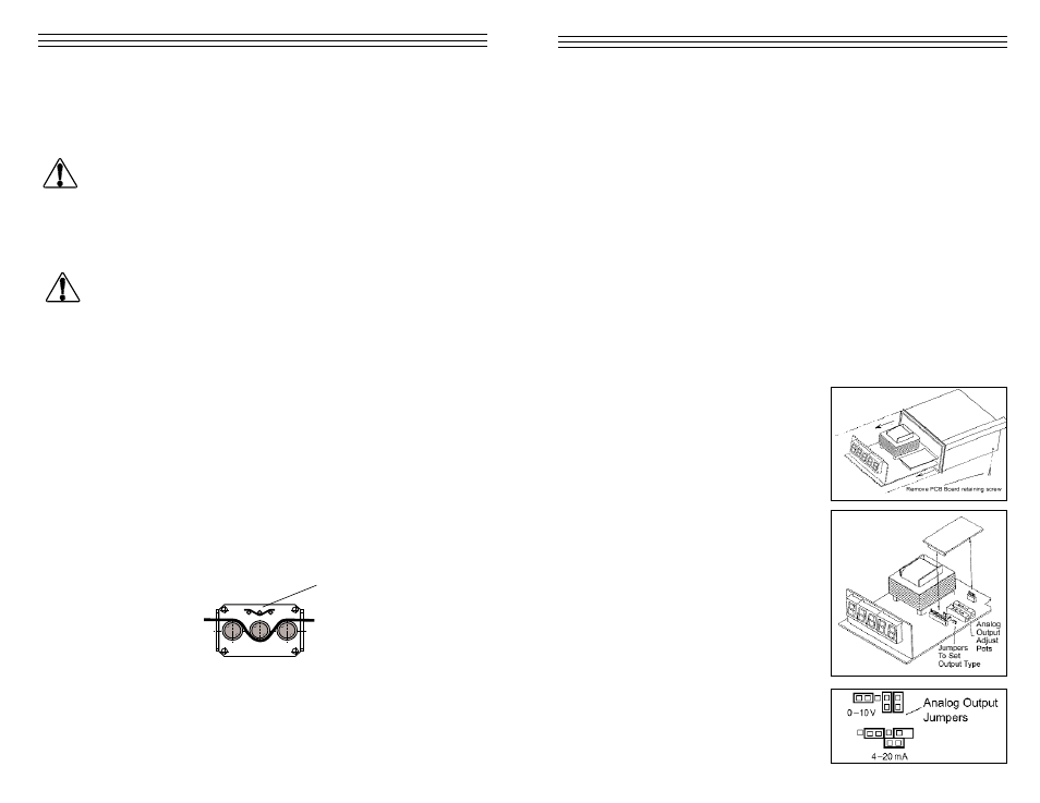
7.1 Changing Analog Output Type
To obtain access to the Analog Output
Adjustment Pots the PC Board must be
removed from the TD-1-TE housing.
1. Unplug all connectors on the rear
side of the unit (sensor, power, etc.)
2. Remove the front cover as
performed during calibration.
3. Remove the PC board retaining
screw located at the bottom of
the housing.
4. Carefully slide out the entire
internal assembly.
5. Remove the Input Card by
grasping it by its edges and pulling
straight up. The three jumpers will
be adjacent to the Analog Output
Adjustment Pots
6. Carefully remove all three jumpers
and re-configure them as shown
in the diagram.