Checkline TD-1-TE User Manual
Page 3
-3-
2 .0 O
V ERV I EW OF T H E
T D-1 -T E I
N DI CAT OR
3 .0 R
EM OV I N G AN D
M
OU N T I N G T H E
F
RON T
C
OV ER
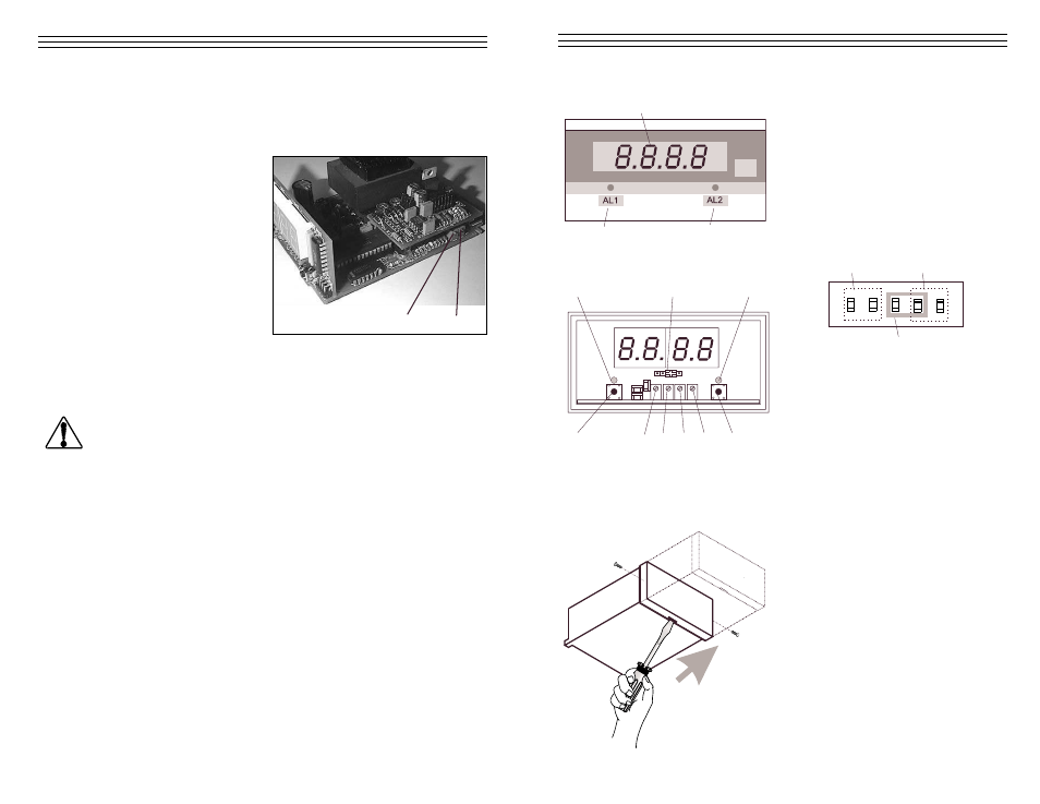
1
2
3
4
2
5
6
7
8
3
9
10
XXX.X
X.XXX
XX.XX
0
1
= Digital
display
0
2
=
Light emitting diode for low
alarm limit
0
3
=
Light emitting diode for high
alarm limit
0
4
=
Decimal point jumper no jumper
set of decimal point XXXX
0
5
=
Pushbutton for low alarm limit
0
6
=
Potentiometer for low alarm
limit
0
7
= ZERO
potentiometer
0
8
= GAIN
potentiometer
0
9
=
Potentiometer for high alarm
limit
10
=
Pushbutton for high alarm limit
Screw
Screw
Removing: Remove the two screws
Insert a screwdriver with a point width
of 4mm in the slot at the bottom of the
housing and carefully push the front
cover away from the panel in the
direction of the arrow.
Mounting: Carefully push the front
cover onto the housing in the opposite
direction of the arrow.
2. Hang a weight that corresponds to 10% of the tension range (pay attention
to the correct unit of measure) from the measured material, vertically, as
shown in the figure on page 12. (Always use a fresh portion of the
material to be measured.)
3. Adjust the potentiometer (13)
using a screw-driver with a
point width of up to 2mm
until the display of the
voltmeter connected to the
Analog interface reads
0.1 volts
-14-
13
14
GAIN Adjustment Procedure
1. Perform a Zero adjustment.
2. Thread the process material through the measuring rollers.
When threading the process material through the rollers, follow the
material path symbol on the front of the sensor. If a force is applied
to the middle sensor roller in the incorrect direction, damage could
result.
NOTE:
Since zero and gain adjustments are always performed
statically, the display values may differ under dynamic load.
3. Hang a weight that corresponds to 95% of the tension range (pay
attention to the correct unit of measure) from the measured material,
vertically as shown in the figure on page 12. (Always use a fresh
portion of the material to be measured.)
4. Adjust the potentiometer (14) using a screwdriver (with a point width
of up to 2mm) until the display of the voltmeter connected to the
Analog interface reads 9.5 volts.
Check the setting and repeat the procedure if necessary.
WARNING