Checkline TD-1-TE User Manual
Page 5
-5-
3. Remove the front cover as
described in Section 3.0
4. Loosen the retaining screw (11) at
the bottom of the housing.
5. Carefully slide out the PC board
from the indicator housing in the
direction of the arrow.
6. Carefully slide the PC board back
into the indicator housing in the
opposite direction of the arrow.
7. Tighten the retaining screw 11 at
the bottom of the housing.
8. Set the front cover back in place
as described in Section 3.0.
11
11
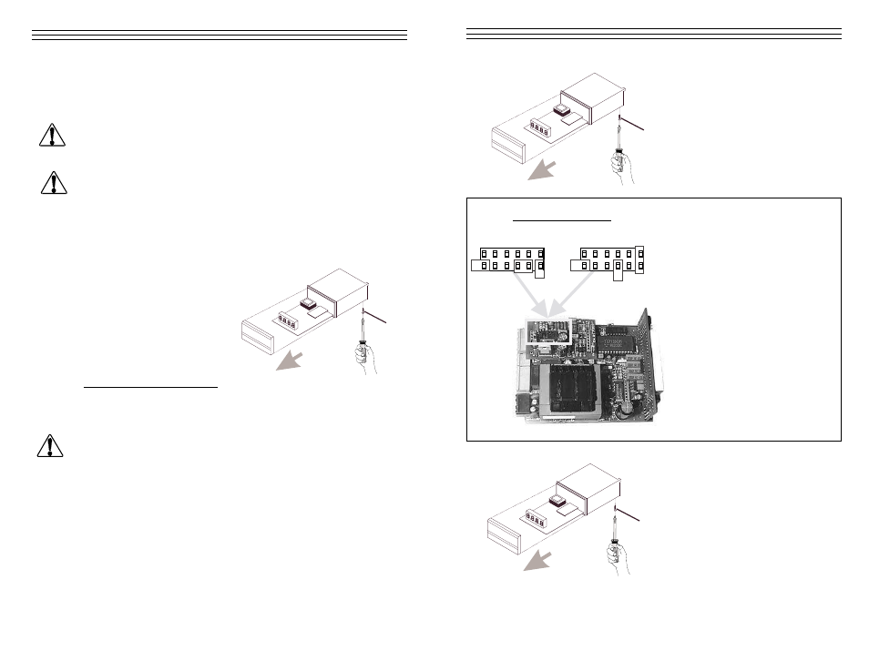
Setting the jumpers:
Damping disabled
Damping enabled
Enable or disable electronic
damping with the jumpers at
the top of the PC board.
-12-
7.2
Zero and Gain Adjustments of the ANALOG Interface
If you change the connected sensor or if you want to fine-tune the
Analog interface you need to recalibrate the interface.
Adjustments to the analog output may only be carried out by
trained electricians whose qualification for performing such work
has been certified in accordance with local regulations.
Only sensors which comply with the specifications given in Section
8.3 may be connected. To avoid random noise and malfunctions,
make sure the cable connecting the TD-1-TE with the sensor is not
laid parallel to powerlines or highly loaded signal lines, regardless
of the type of voltage.
1. Remove the front cover following the instructions outlined in
Section 3.0.
2. Loosen the retaining screw
(11) at the bottom of the
housing.
3. Carefully slide out the PC
board from the indicator
housing in the direction of
the arrow.
Preparations for Calibration
1. Connect the TD-1-TE with sensor to be used in accordance with
the pin assignment illustrated in Section 8.2.
Only sensors which comply with the specifications given in Section
8.3 may be connected. To avoid random noise and malfunctions,
make sure the cable connecting the TD-1-TE with the sensor is not
laid parallel to power lines or highly loaded signal lines, regardless
of the type of voltage.
.
WARNING
WARNING
WARNING
11