Checkline TD-1-TE User Manual
Page 4
-4-
4 .0 S
ET U P
4.1 Setting the Decimal Point (Refer to the diagrams in Section 2.0)
The decimal point is factory-set to the supplied sensor. If the indicator
unit is supplied without a sensor or after changing to a sensor with a
different tension range, the decimal point jumper (4) must be set to the
sensor's tension range as follows:
1. Remove the front cover as described in Section 3.0.
2. Set the jumper for decimal point display to the desired position (4)
4.2 Setting the Low Alarm Limit (Refer to the diagrams in Section 2.0)
1. Remove the front cover as described in Section 3.0.
2. Connect the TD-1-TE to the power supply and switch on.
3. Press the pushbutton (5) and use a screwdriver with a point width of
2.5 mm to turn the potentiometer (6) to the desired low alarm limit.
Keep the pushbutton (5) depressed while adjusting the pot. At the
same time, the digital display (1) shows the set low alarm limit.
4.3 Setting the High Alarm Limit (Refer to the diagrams in Section 2.0)
1. Remove the front cover as described in Section 3.0.
2. Connect the TD-1-TE to the power supply and switch on.
3. Press the pushbutton (10) and use a screwdriver with a point width
of 2.5 mm to turn the potentiometer (9) to the desired high alarm
limit. Keep the pushbutton (10) depressed while adjusting the pot. At
the same time, the digital display (1) shows the set high alarm limit.
4. Then set the front cover back in place as described in Section 3.0.
4.4 Enabling and Disabling Electronic Damping (Refer to the diagrams
in Section 2.0)
1. The indicator unit is shipped from the factory with the damping
disabled. To enable damping follow this procedure
2. Make sure the TD-1-TE is switched off and all plug connections on
the rear side of the device are disconnected.
-13-
When power is switched on, a voltage of 115 V is applied to the PC
board which is not protected against accidental contact when
removed from the housing. For this reason, calibrating the analog
output may only be carried out by trained electricians whose quali-
fication for such work has been certified in accordance with local
regulations.
2. Connect a voltmeter to the ANALOG interface.
3. Connect the power supply in accordance with the pin assignment of
Section 8.2.
4. Switch on the power to the TD-1-TE.
5. Allow approx. 10 minutes for thermal stabilization of the unit.
ZERO Adjustment Procedure
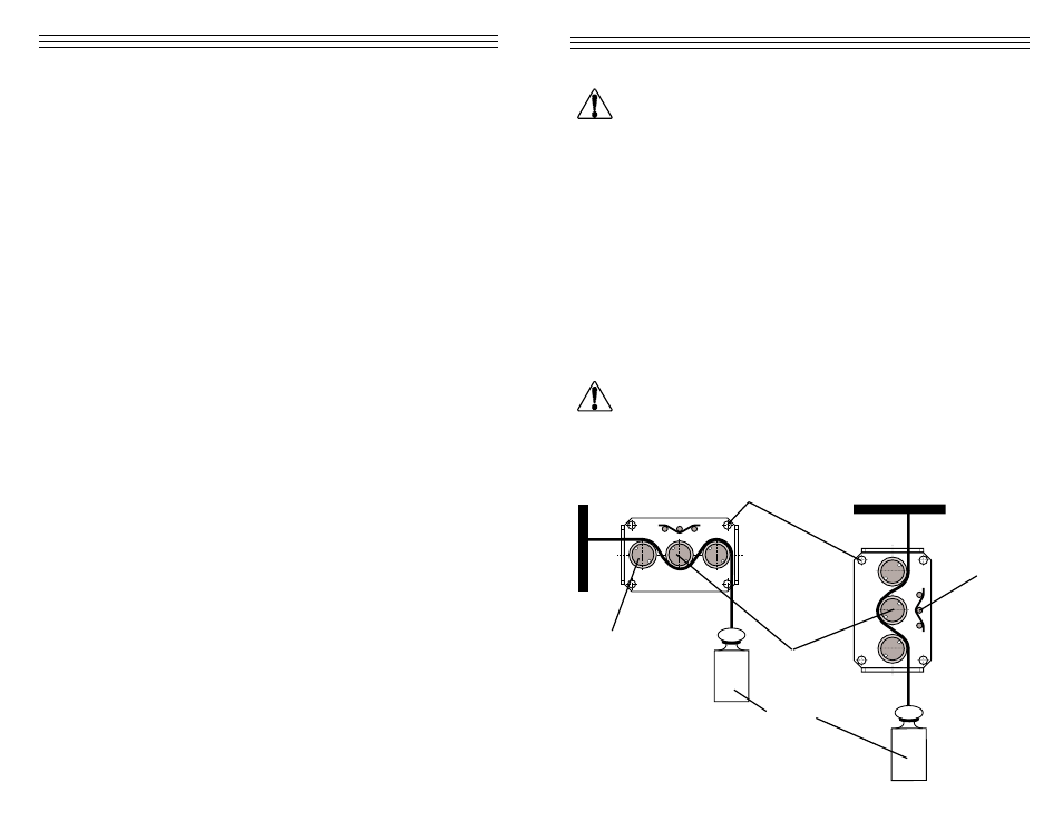
1. Thread the process material through the measuring rollers, following
the red marking on the front of the sensor.
When threading the process material through the rollers,
follow the material path symbol on the front of the sensor. If a force
is applied to the middle sensor roller in the incorrect direction, dam-
age could result.
NOTE:
Since zero and gain adjustments are always performed
statically, the display values may differ under dynamic load.
WARNING
WARNING
Mounting holes 4 x
W
eight
Material path
symbol
Measuring
roller
Guide rollers 2x