4 function, The load cell – Checkline RTM 20D User Manual
Page 6
4 Function
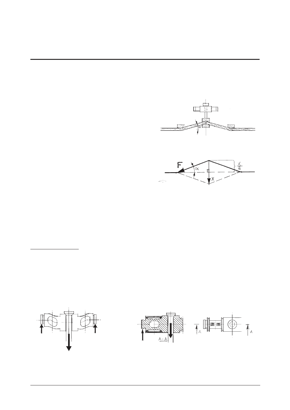
By means of the tightening device of the centre support the rope is forced to decline ac-
cording to figure 4:1. The angle will always be the same, as the rope is pressed against
the fixed centre support by means of the
clamping jaw. Even if the rope diameter is
changed, the angle will stay the same.
A resultant force is then obtained, perpen-
dicular to the main direction of the rope, see
figure 4:2.
sin
a =
X/2 x 1/F
X = sin
a
x 2F
Angle
a
= 1.43°, gives:
sin
a
= 0.0250 = 1/40
X = 1/40 x 2F
X = 1/20 x F
i.e. ratio 20:1
The resultant force affects the pull rod which is firmly connected with the flat centre sup-
port. The pull rod affects in its turn the load cell, which gives an electrical signal which is
proportional to the force. The signal is amplified, converted and indicated on the LCD
display of the instrument.
The Load Cell
The load cell is of the type “parallelogram of flexible beam” in toughened steel. It is pro-
vided with four adhesive type strain gauges (foil gauges), where all the wires are in the
same longitudinal direction (figure 4:4).
The load cell has supports in the end points and will therefore bend when the pull rod is
loaded (figure 4:3).
5(12)
RTM 20 D - Users Manual
BA 7047be
ba7047be.vp - 040216
4:1
4:2
4:3
4:4