3 damper, installation – BUCHI Ultrasonic Package User Manual
Page 26
5 | Installation
BÜCHI Labortechnik AG
26/46
Ultrasonic Controller
5.
Connect the feed tube (8) to the Ultrasonic nozzle (connector (b)) while in
tegrating the damper into the tube. (See below)
6.
Connect the spray gas (compressed air or nitrogen), as provided by the in
stallation of the B290, to the nozzle (connector (a)). The spray gas will
serve as cooling gas for the nozzle.
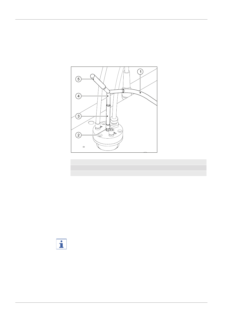
5.3 Damper, installation
Fig. 11: Installation of the damper
1
Feed tube (long part)
2
Connector for feed solution
3
Feed tube (short part)
4
Ypiece
5
Damper
The damper is integrated into the feeding tube. To install it proceed as follows:
1.
Select the suitable type of tube for the feed solution.
2.
Prepare a piece of tube of the adequate length for the connection between
the feed solution vessel on the product feed table and the corresponding
connector (2) of the ultrasonic nozzle.
3.
Cut of a short piece of the prepared tube (3).
4.
Connect the ypiece (4) to the longer part of the feed tube (1) and the
shorter part (3), as described above.
5.
Slide the damper (5) on the free connector of the Ypiece (4).
6.
Insert the free end of the feed tube into the feed solution vessel. Make
sure in dips into the solution.
NOTE
The damper can also be used to remove a slight blockage in the nozzle by sim
ply squeezing it. This will generate a short overpressure impulse that in some
cases is sufficient to remove the blockage.