1 nozzle, power settings – BUCHI Ultrasonic Package User Manual
Page 18
4 | Description of function
BÜCHI Labortechnik AG
18/46
Ultrasonic Controller
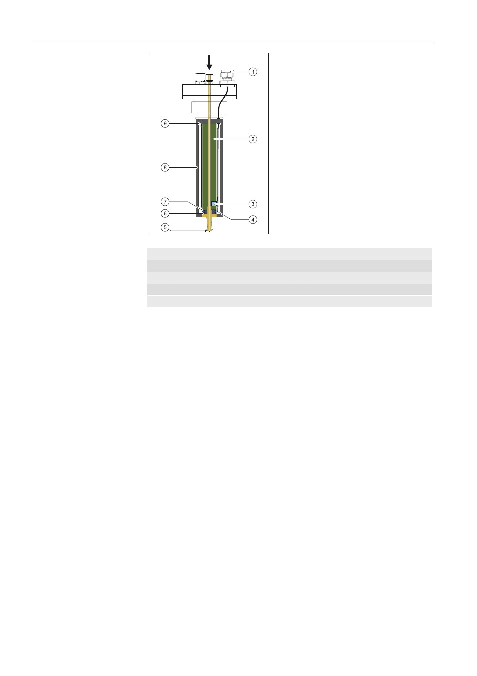
Fig. 4: Nozzle design (schematic)
1
Electrical connector
2
Rear horn
3
Temperature sensor
4
Active electrode
5
Atomizing surface
6
Piezoelectric transducer
7
Ground electrode
8
Housing
9
Ground lug
Discshaped ceramic piezoelectric transducers convert high frequency electrical
energy from a power generator into vibratory mechanical energy at the same
frequency.
The transducers are sandwiched between 2 titanium cylinders, which act to
concentrate and amplify the vibration, maximizing it at the atomizing surface. Ti
tanium is used because of its good acoustical characteristics, corrosionresis
tance and high strength.
The liquid is delivered to the atomizing surface through a large diameter feed
tube that runs the length of the nozzle. The large liquid feed orifice assures free
dom from clogging.
4.2.1.1 Nozzle, power settings
The ultrasonic atomization process is highly dependent on the power delivered
to the nozzle. Best results are achieved within a relatively narrow input power
range. Below a critical power level, referred to as the “stall point”, there is insuf
ficient energy to produce atomization. The power range in which atomization
proceeds normally is generally confined to a narrow region, approximately 0.5–
1.5 Watt above the stall point. At power levels above this range, the liquid is lit
erally “ripped apart” by the excess energy provided, causing large chunks of
material to be expelled, rather than the characteristic soft spray of fine drops.
This condition is known as cavitation.
The actual power at which the stall point occurs is dependent on several fac
tors:
• Nozzle type (mechanical and electrical characteristics, size)
• Liquid characteristics (e.g. viscosity, solids content)
• Flow rate
• Size of the atomizing surface