Brookfield Temperature Controller, Model 106 User Manual
Page 6
Brookfield Engineering Labs., Inc.
Page 6
Manual No. M/02-207-C009
IV. INSTALLATION
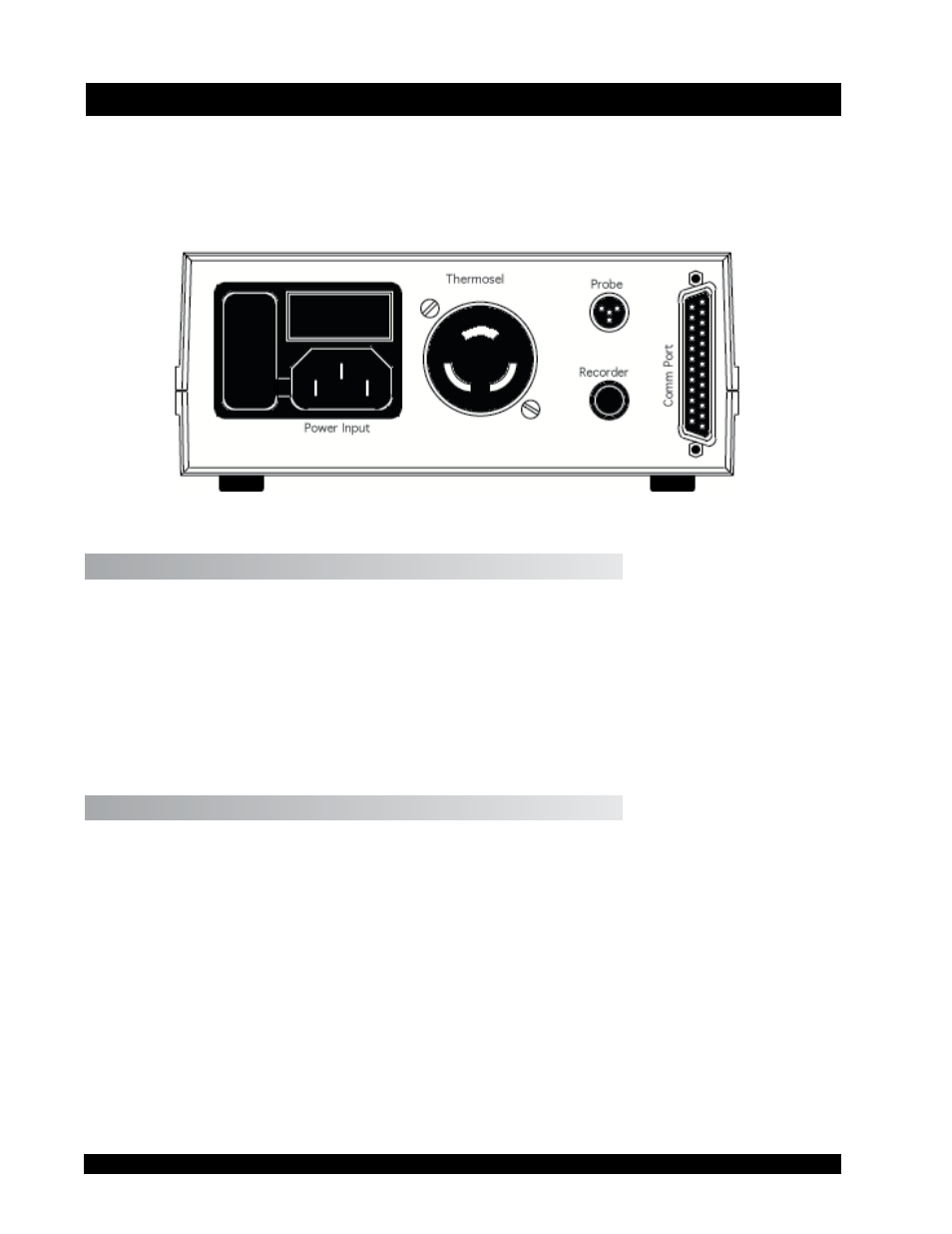
Plug the temperature sensor into the Probe receptacle, the Thermo Container into the Thermosel
receptacle, the strip chart recorder (if used) into the Recorder jack and a remote RS-232C device
(again, if used) into the Comm Ports 25-pin plug. The rear panel will appear as follows in
Figure IV.1.
Figure IV.1
IV. Probe
The probe is a 100 ohm precision platinum RTD (resistance temperature detector) probe (Brook-
field Part Number DVP-94Y) which is plugged into the Probe port on the rear panel.
Note: The RTD Probe must be plugged into the Programmable Temperature Controller and
the RTD Probe end must be inserted into the Thermo Container before power is turned
on. The Controller will beep on/off. An error message (0.RTD) will be displayed if
the Programmable Temperature Controller is turned on and the RTD Probe is not in-
stalled.
IV.2 Recorder
The Recorder jack provides a signal to a recording device (the optional HT-88Y cable is provided
for this service) such as a strip chart recorder. The full scale recorder output signal range is from
0 to 4 V for the Thermosel systems. The temperature can be obtained from the output potential
(in mV) as follows:
The 0 to 4 volt output corresponds to a temperature range of -100°C (-148°F) to 300°C (572°F).
Realistically, temperatures in Thermosel systems will typically be above ambient. Therefore,
output voltages will generally range from slightly less than 2 volts (<100°C) to the full 4 volts
(300°C). The temperature corresponding to any intermediate output voltage can be obtained from
the following:
(0.1 * mV) -100 = °C (Centigrade Temperatures)
(0.18 * mV) -148 = °F (Fahrenheit Temperatures)