B.5.4 flow diagram for zero calibration – Brookfield R/S CPS Rheometer User Manual
Page 59
Brookfield Engineering Labs., Inc.
Page 59
Manual No. M08-218-B0212
Other Faults
Indication
Possible Cause
Solution
Dial indicator reading
is inconsistent.
Set pin has lost hold power.
Pin may need to be replaced. Call for
service.
Viscosity reading is
low.
Micrometer ring was not lined
up with zero on shaft. Head
is too high.
Ensure spindle is not mounted to
R/S. Re-try zero calibration. If it
fails, call for service.
Viscosity reading
is low and spindles
does not mvoe freely
when hex nut is
disengaged.
Contamination has entered
the gap between the spindle
cone piece and spindle shaft.
Loosen set screw. Extend spindle
to maximum length. Clean shaft.
Repeat if needed. If the spindle can-
not be cleaned sufficiently, call for
service of spindle.
Viscosity reading is
low.
Rheometer has been placed
in a drafty location.
Utilize solvent trap; shield unit from
drafts.
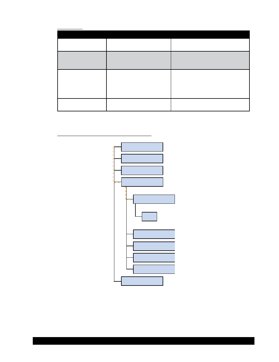
B.5.4 Flow Diagram for Zero Calibration
Zero-Calibration
OK
Utilities
Edit Programs
Print Programs
Measuring System
Print Memory
Run Program
Remote
Configuration
Run Single