B.3 setting the gap – Brookfield R/S CPS Rheometer User Manual
Page 55
Brookfield Engineering Labs., Inc.
Page 55
Manual No. M08-218-B0212
1. Turn on the R/S-CPS+ Rheometer.
2. Turn on the temperature controller. Set the controller to 25°C.
3. Allow the R/S-CPS+ Rheometer to be on for a minimum of 10 minutes prior to taking
measurerment data or running a zero calibration.
• Zero Calibration does not have to be executed prior to every test, but should be run no
less than once a week.
• Zero Calibration takes approximately eight (8) minutes.
• Best Practice: run the R/S-CPS+ Rheometer at 100 rpm for 30 minutes just prior to
zero calibration.
4. Ensure the spindle is not installed on the R/S-CPS+ Rheometer.
5. Lower the rheometer head.
6. Lower the spindle coupling collet.
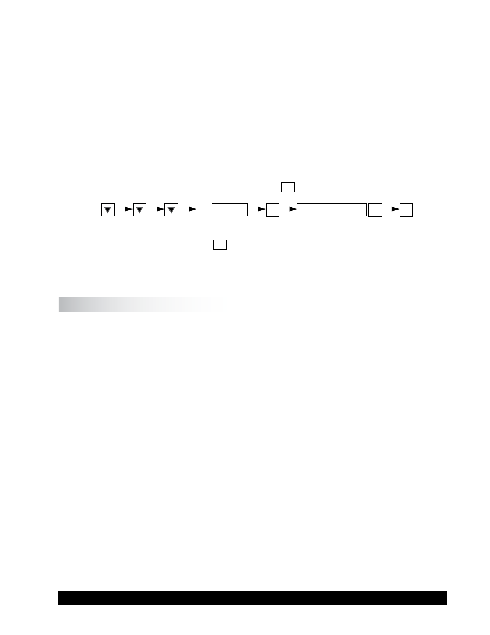
Select the zero calibration option and push the
OK
button.
OK
OK
OK
to UTILITIES
ZERO CALIBRATION
7. Upon a successful completion of the zero calibration procedure, the rheometer head will
display a message. Press the
OK
key to save the information. If an error message appears,
see Appendix B.5.3: Troubleshooting. If the problem cannot be fixed, contact Brookfield
or an authorized dealer for troubleshooting advice.
1. Raise the rheometer head (handle forward).
2. Attach the designated spindle on the rheometer.
3. Loosen the set screw so the spindle shaft cone moves freely up and down by hand.
4. Lower the rheometer head so spindle and plate are in contact.
5. Allow the spindle to come to temperature.
NOTE: The greater the difference between the test temperature and ambient, the greater
the time to come to temperature.
6. Raise the rheometer head.
7. With the rheometer head up, turn the micrometer ring to the zero point. Confirm this by ob-
serving the horizontal line on the instrument column and the vertical line on the micrometer
ring line up as crosshairs. Turning the micormeter ring clockwise lowers the head; turning
the micrometer ring counter-clockwise raises the head.
8. Move the micrometer ring clockwise past zero by one half revolution.
9. Move the micrometer ring counter-clockwise to the zero position and stop there.
NOTE: AFTER THIS STEP, NEVER TURN THE MICROMETER RING CLOCKWISE.
A PRECISE GAP SETTING CANNNOT BE ASSURED OTHERWISE.
If the micrometer ring IS turned clockwise after this step, the gap setting procedure
will need to be repeated starting from Step 7.
10. Lower the rheometer head (by moving the handle away from you), so that the spindle
makes contact with the bottom plate of the rheometer base and the rheometer head is bot-
tomed out on the micrometer ring.
B.3 Setting the Gap