Adaptive Technologies UB-225-9 User Manual
Page 2
©2013 Allen Products Co., Inc. Signal Hill, CA 90755
(562) 424-1100
-REV00-072613
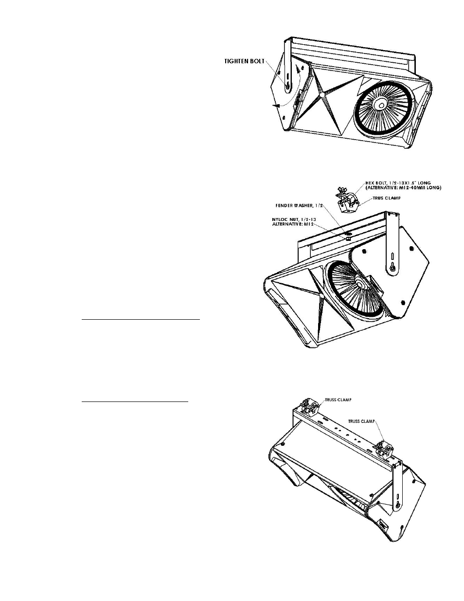
Figure 2
Figure 3
Figure 4
Step 2:
Select the mounting area where the
loudspeaker will be installed. Attach
the U-Bracket to the wall or ceiling
using the holes on the base of the U-
Bracket. Use the appropriate
hardware for the application (if in
doubt, consult a local hardware
specialist). Tighten permanently.
Step 3:
Check the speaker’s insert threads if
it metric or US standards.
Place the speaker between the U-
Bracket’s arms. Insert the M10
Button head bolt, flat washer and
split lock washer (must match the speaker’s
thread) through the hole in the arms with the
sound isolation gasket in between the speaker
and the bracket. Thread the bolt into the
loudspeaker. Repeat on the other side of the
speaker (Figure 1). Do not fully tighten yet.
Note: If the mounting insert of the
speaker is 3/8-16 use the 3/8-16x1.75”
long button head screw.
Step 4:
Rotate the loudspeaker into the desired
direction then tighten the side bolts
permanently (Figure 2).
Step 5:
Truss Clamp Application:
For a single truss clamp application, attach the
truss clamp on the center hole of the U-
bracket’s base using a ½-13x1.5” long hex
bolt, ½ fender washer and a ½-13 nylock nut
(M12 hex bolt, M12 fender washer and M12
nylock nut can also be used). Position the
desire direction of the loudspeaker then tigthen
nut (figure 3).
For dual truss clamp application, attach the
truss clamp on the two holes of the u-brackets
base close to the bend. Use ½-13x1.5” long
hex bolt, flat washer and nylock nut (M12 bolt,
fender washer and nyloc nut can also be used)
(Figure 4).
Step 6:
Recommendation: Safety Cable
Install a safety cable to the U-Bracket and to
the structurally load rated mounting surface.