Adaptive Technologies SBC3-8-CA-20 User Manual
Page 2
© 2010 ATM Fly-Ware Signal Hill, CA
90755
(562)
424-1100
06/07/10
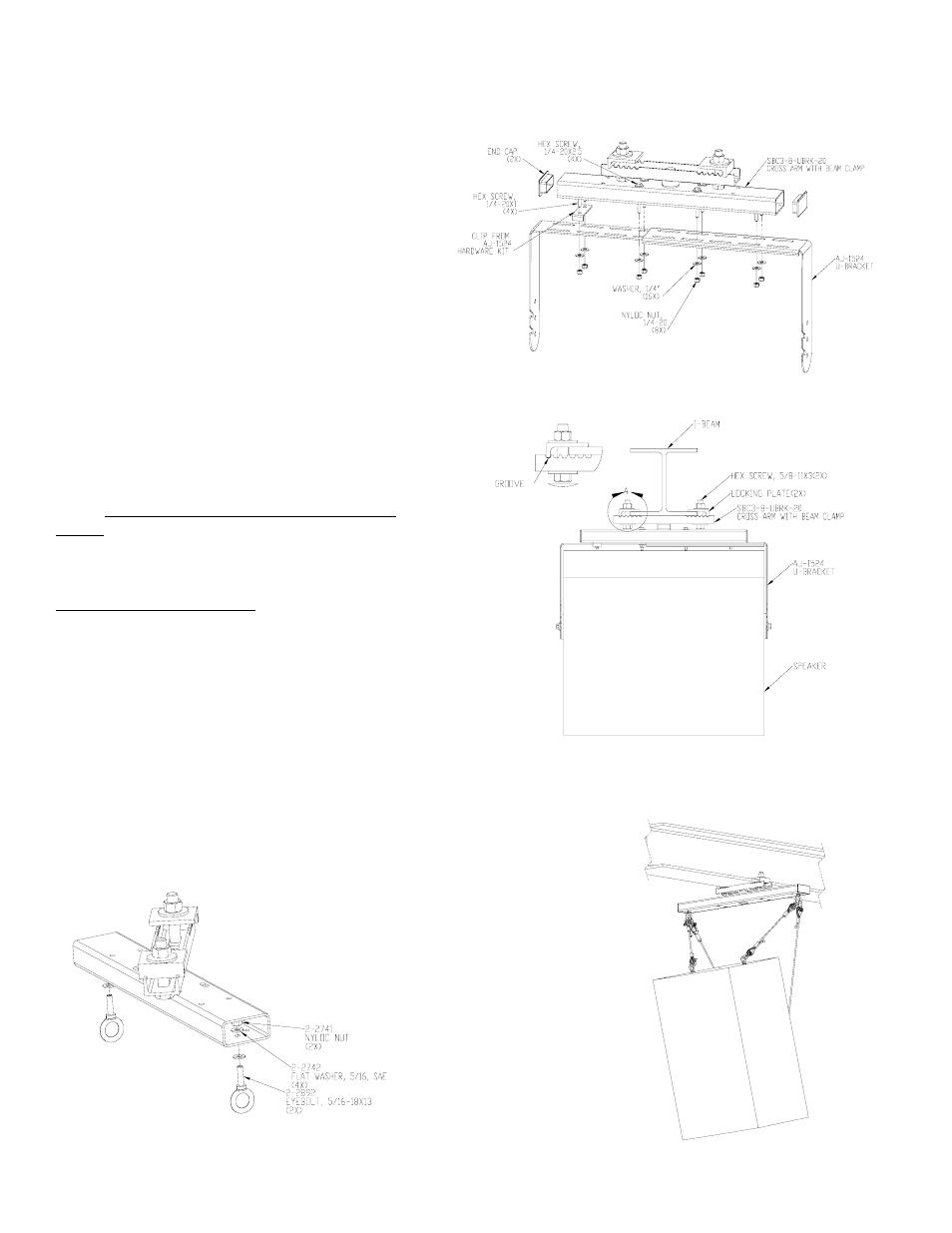
Step 3.
Attached the swivel beam assembly to the
attachment I-beam. Adjust the Locking plate so that
the bolts of the locking plates are a close or
touching to the sides of the I-beam. Make sure that
the locking plate is also secure and resting on the
grooves of the channel. Make sure the beam clamps
channel is centered to the attachment I-beam.
Clamp the locking plates tightly to the beam both
vertically and horizontally with the 5/8” bolts,
washers and nuts. Add loctite thread compound to
the threads of the bolts over the nut (Figure 4).
Step 4.
Put on the two end caps for the cross arm (Figure
2, 3).
Step 5.
Attach the speaker to the AJ-1524 adjustable u-
bracket with the hardware kit that comes with it.
Adjust the tilt angle and tighten the screws on the
sides. Refer to AJ-1524 product instruction
sheet.
For suspending speakers:
Step 1.
To Suspend a speaker to the cross arm, install the
eyebolts to the center holes of the cross arm close to
the edge. Use load rated hardware to suspend the
speaker (Figure 5 and 6).
Step 2.
Install the hole plug to the center hole on the bottom of the tube.
Step 3.
Repeat step 3 and 4 to attach the Swivel beam clamp to the I-Beam.
Figure 3
Figure 4
Figure 5
Figure 6