Adaptive Technologies PM-SA-24 User Manual
Page 2
© 2008 Allen Products Company, Signal Hill, CA 90755 USA (562) 424-1100
REV02-042710
Step 3. Strapping the Support Arm and Adapter to a pole
Decide the final horizontal pan angle of the support arm then, using the instructions from the selected PoleStar Band Kit,
secure the Support Arm to the column permanently (See Band Kit Instruction sheet).
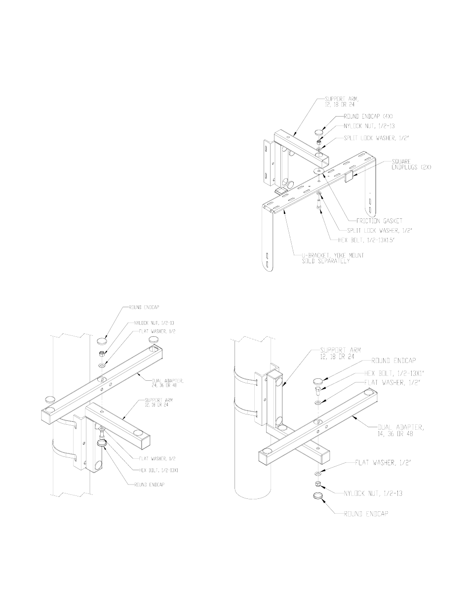
Step 4 Attaching a Mount to the Support Arm.
Attach the selected mount’s center hole to the Support Arm’s
end hole using the included ½-13 x 1.5” hex bolt, split lock
washer and nylock nut. Make sure the friction washer is
placed in between the support arm and the yoke. Allen/ATM U-
Brackets and Dual Adapters Kits shown in Fig. 3, 4 and 5.
Step 5. Install and Aim Speaker(s)
Following the instructions of the mount, install and aim
loudspeaker then tighten hardware and angles permanently.
Step 6. Install End Caps and plugs:
After installation, cover the end of the pole arm with the 2 x 2
end caps and the round holes with the round hole plugs. Trim
end caps if necessary to clear bolts head and washers (Fig.3).
Step 7. Install Safety Cable
Secure a safety cable to the pole or column, and then attach
the other end of the safety cable to the speaker to bypass the
mounting system.
Fig. 3
Fig. 4
Fig. 5