Adaptive Technologies MM-024-BT User Manual
Page 2
2002 APC Incorporated, Signal Hill, CA 90755 USA (562) 424-1100 07/24/02
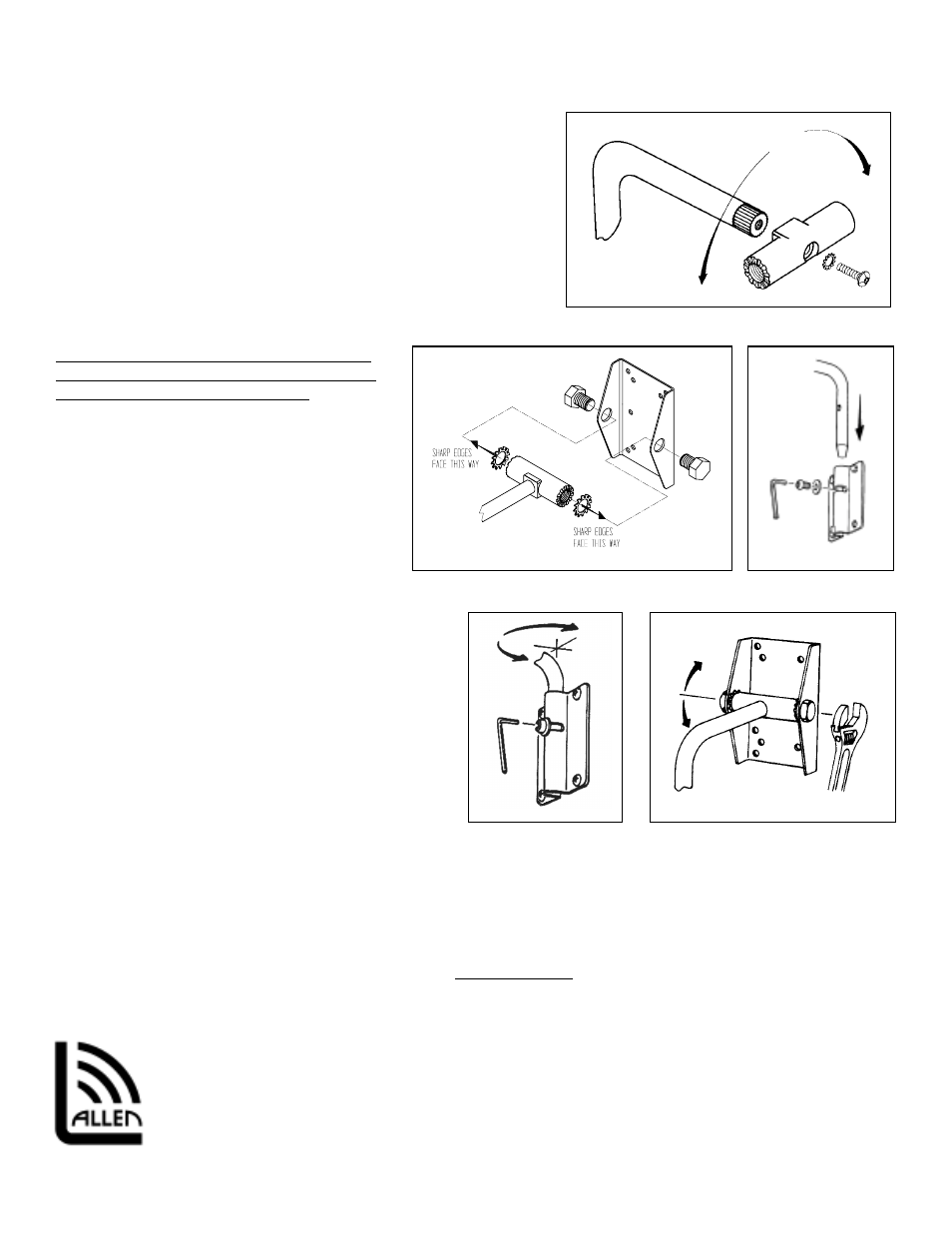
Figure 3
Figure 4
Figure 5
Step 3.
For vertical applications, use the support arm with the pivot rod
attached to the support arm as is. For horizontal (no tilt) installations,
remove the pivot rod from the support arm assembly by removing the
socket head screw (Figure 3). Reattach the pivot rod at the desired
angle then secure permanently with the socket screw.
Step 4.
Assemble the support arm to the adapter plate by bolting the pivot rod
inside the flanges of the speaker adapter plate with the star washer in
between the flange and the pivot rod. The rounded surface of the star
washer’s teeth must seat against the pivot rod (Figure 4).
Important:
The sharp edges of the star washer must face
the inside surface of the speaker adapter plate
flanges to achieve proper tilt locking.
Step 5.
Thread the 3/4”-16 hex bolt through the side
holes of the adapter plate’s flanges and into the
pivot rod. Position the support arm perpendicular
to the adapter plate then tighten securely but not
permanently. This will hold the speaker in
position while mounting it to the wall or ceiling
(figure 4).
Step 6
Lift the speaker and support arm up to the
mounting plate and insert the arm through the end of the
mounting plate with the cross slot (Figure 5). Line up the
support arm’s threaded hole with the cross-slot. Insert
the 5/16” socket screw and 5/16” flat washer through the
mounting plate’s slot and into the threaded hole of the
support arm. Tighten the screw firmly but not
permanently (figure 5). Be sure the flat washer seats
outside the slot.
Step 7.
Setting the pan angle
Loosen the socket screw on the wall plate (do not
remove). Rotate the speaker horizontally right or left
until the speaker is aimed in the desired direction.
Permanently tighten the socket screw at the mounting
plate with a 3/16” hex wrench (figure 6).
Step 8.
Setting the tilt angle
While supporting the speaker’s weight, loosen the 3/4” hex bolts at the sides of the speaker adapter plate (do not
remove). Lift the speaker up to the desired tilt angle and hold it in position while re-tightening the 3/4” hex bolts. Be sure
that the screws have been tightened permanently before releasing the weight of the speaker (Figure 7).
If the tilt angle needs to be adjusted,
DO NOT PULL ON SPEAKER
, rather repeat step 8.
Figure 6
Figure 7
Allen Products Company Inc.
1635 E. Burnett Street
Signal Hill CA 90755 USA
Tel: (562) 424-1100 Fax: (562) 424-3520
Web Site: www.allenproducts.com