Access to components – 360 Systems MAXX-2400SD User Manual
Page 94
____________________________________________________________________________________
Page 94
MAXX 2400 Owners Manual
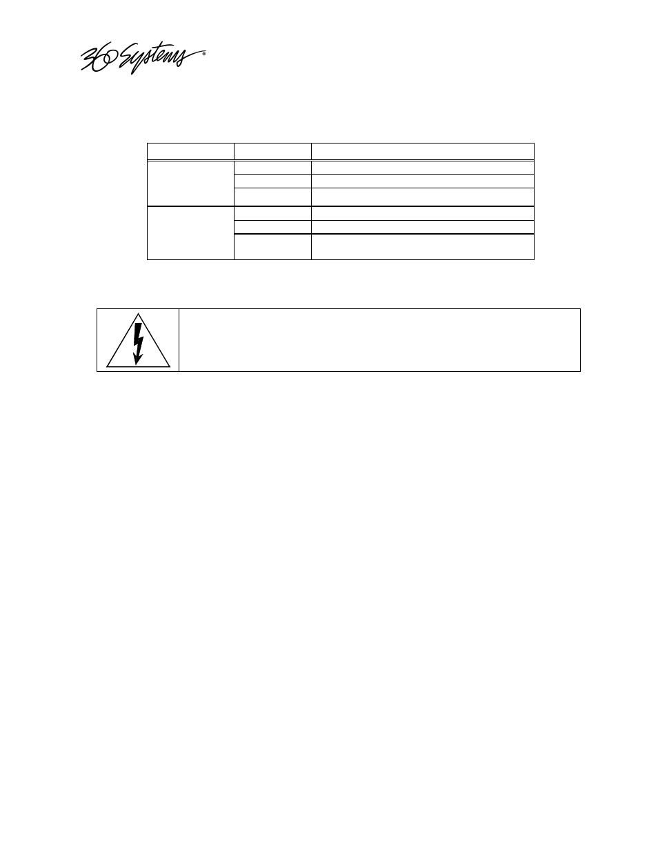
Gigabit Ethernet Indicators
The Gigabit Server Adapter card has the following indicator lights:
Label
Indication
Meaning
Green on
The port is connected to a valid link partner
Green flashing
Data activity
ACT/LNK
(Left)
Off
No link
Off
10 Mbps
Green
100 Mbps
10=OFF
100=GREEN
1000=YELLOW
(Right)
Yellow
1000 Mbps
ACCESS TO COMPONENTS
Be certain to shut down the Image Server, turn off the rear panel power switch
and disconnect both power cords before opening the unit for service.
The following sections provide instruction on disassembly and re-assembly for maintenance.
The front panel is removed to access the internal CD-ROM drive (for system program updates), or
to service the hard drives.
The top cover is removed to access the analog/digital audio selection jumpers, or to service an I/O
card, the system board, or power supply.
Deploying the Front Panel
The front panel is easily deployed for access to the CD-ROM drive, the twelve disk drives, or for
removing the server from an equipment rack. Using a coin or a flat-blade screwdriver, unscrew
the two large panel fasteners on the left and right sides of the face panel. Pull forward and down to
deploy the front panel in the open position
To replace the front panel, push upward and toward the unit. Screw the front panel fasteners back
into the chassis. Tighten the front panel access screws with a screwdriver.
Removing the Top Cover
To remove the top cover, Press on the two blue release buttons on the top cover and slide back,
then lift up.