Appendix f – gpio interfacing – 360 Systems MAXX-2400SD User Manual
Page 120
____________________________________________________________________________________
Page 120
MAXX 2400 Owners Manual
APPENDIX F – GPIO INTERFACING
GPIO Connectors
General purpose control inputs (GPI) may be applied to the GPIO port, which is a DB-25-F
connector. These inputs are optically isolated from the MAXX 2400 circuitry; individual floating
returns are provided. +5 volts may be sourced from pins 21 or 22, or provided from an external
source. Current limiting devices are provided within the MAXX 2400.
General purpose outputs also appear on the GPIO connector. Open-collector outputs are
provided as status outputs, and may be used to drive an external LED or control input.
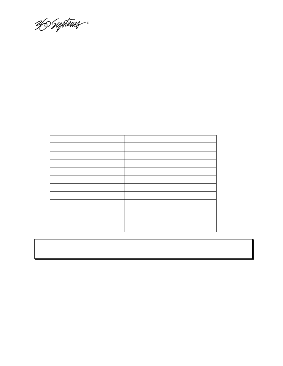
Refer to the connector pin-out table and partial schematic, following.
GPIO Connector Pinout
Numbers in parentheses indicate numbering of signals on GPIO Connector 2
Pin
Signal
Pin
Signal
1
GPI 1 (7)
14
GPI 1 (7)
RTN
2
GPI
2
(8)
15
GPI
2
(8)
RTN
3
GPI
3
(9)
16
GPI
3
(9)
RTN
4
GPI
4
(10)
17
GPI
4
(10)
RTN
5
GPI
5
(11)
18
GPI
5
(11)
RTN
6
GPI
6
(12)
19
GPI
6
(12)
RTN
7
N/C
20
N/C
8,
9,
10
GND
21,
22
+5V
S
OURCE
(200
M
A
MAX
)
11
GPO
2
(8)
23
GPO
1
(7)
12
GPO
4
(10)
24
GPO
3
(9)
13
GPO
6
(12)
25
GPO
5
(11)
Warning: Incorrect wiring of GPI connector may damage GPI interface circuitry.