Input channels, O mic/line switch (rear panel), Channels 1 & 2 – Yamaha AM602 User Manual
Page 5: O gain control — channels 1 & 2, 0 eq lo & hi controls — channels 1 & 2, O aux controls, 0 pan control, 0 channel fader, Note
Attention! The text in this document has been recognized automatically. To view the original document, you can use the "Original mode".
CONTROLS
• Input Channels
o
MIC/LINE Switch (Rear Panel)
— Channels 1 & 2
This switch sets the input sensitivity of the corre
sponding input to match line-level or microphone-level
input sources. If you will be connecting a line-level
source such as an electronic keyboard or audio
equipment, set the switch to LINE. If you will be con
necting a microphone or other low-level source, set
the switch to MIC.
O GAIN Control — Channels 1 & 2
This control adjusts the input sensitivity of the corre
sponding input channel. Continuously variable gain
control allows optimum matching with virtually any
microphone or line source.
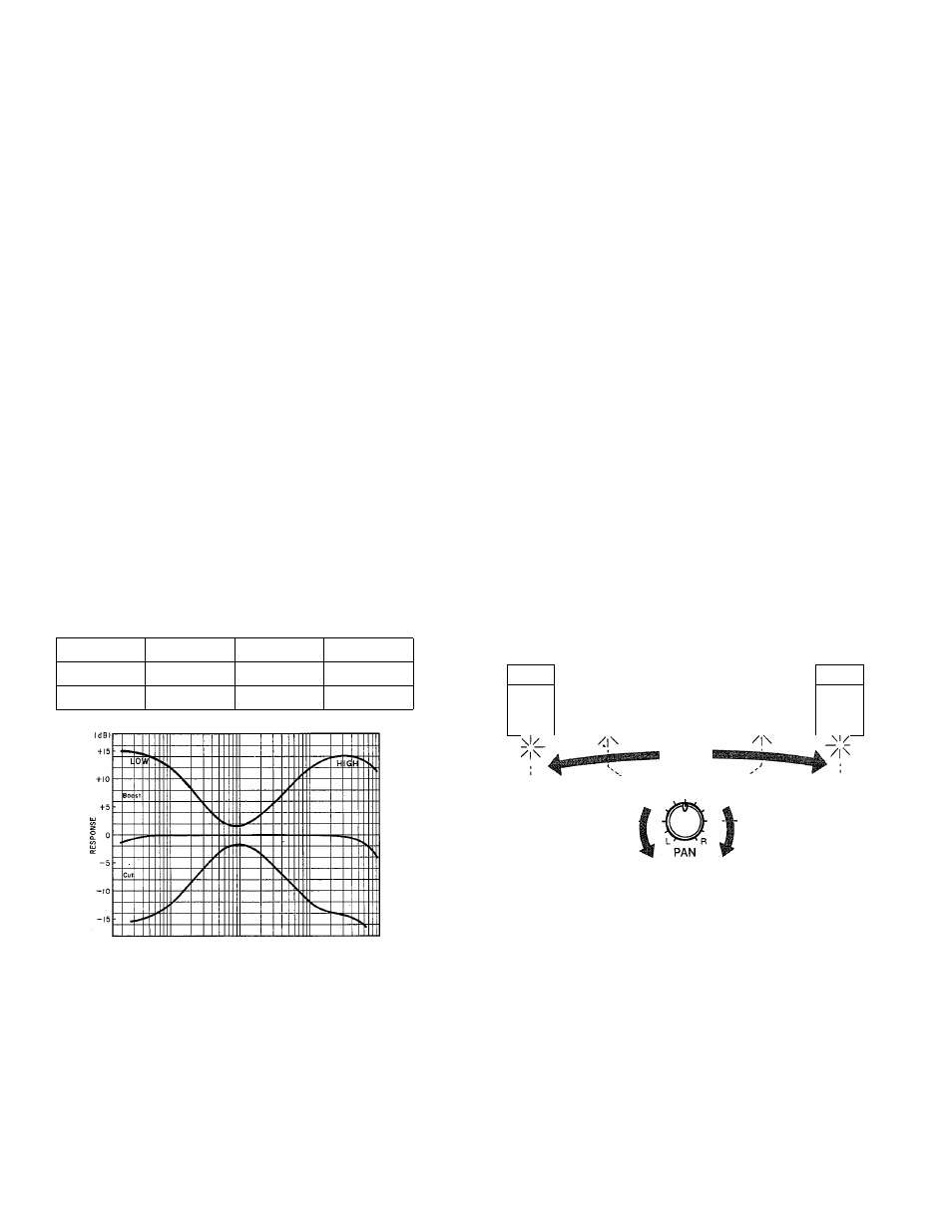
0 EQ LO & HI Controls — Channels 1 & 2
These controls permit individually modifying the re
sponse of each channei. The HI and LO EQ controls
function as follows:
Control
Range
Freq.
Type
HI
+15 dB
10 kHz
Shelving
LO
±15 dB
100 Hz
Shelving
Ik
FREQUENCY
o AUX Controls
The AUX 1 and AUX 2 controls on the AM602 deter
mine the level of the signal sent from that channel to
the AUX 1 and AUX 2 mixing busses, respectively.
The AUX mixing busses then feed the corresponding
AUX SND level controls and finally the corresponding
rear-panel AUX SND output jacks. The channel AUX
controls can be used to produce two independent
mixes to feed external effect devices, a performer’s
headphone cue system or other system fed by the
AUX SND jacks. All AUX controls are “post-EQ/post-
fader,” meaning that their signal is derived from a
point after the channel EQ stage and fader. This
means that the AUX signal is affected by the channel
EQ and fader settings.
0
PAN Control
The PAN controls assign the signal from the corre
sponding channel to any desired position in the "ste
reo sound field.” If a PAN control is set to the maxi
mum “L” (LEFT) position, the signal from that channel
will appear only at the left-channel output (ST QUT L).
If the PAN control is set fully “R” (RIGHT), the signal
will appear only at the ST QUT R output jack. If a
PAN control is set to its center position, then the sig
nal from that channel will appear equally at both the
left- and right-channel outputs, and the sound will
appear at the center of the stereo sound field (at a
point midway between the two stereo speakers).
Qther PAN control settings place the sound at posi
tions roughly corresponding to the PAN control setting
by varying the level of the signal sent to the left- and
right-channel outputs.
LEFT
RIGHT rxi
SPEAKER
SPEAKER
\l/
\l/
/|\
\l/
0
Channel Fader
This is the main level control for each input channel. It
determines the level of the signal sent from the corre
sponding input channel to the master stereo buss.
The settings of the input channel faders determines
the “mix” or balance of sound levels between the in
struments or other sources connected to the inputs.
NOTE: ---------------------------------------------------
If a channel is not being used, its fader should be
set to the minimum position to prevent unwanted
noise from being added to the main program sig
nals.