Pin assignment, External view, Pin assignment external view – Panasonic PANASYNC/PRO TX-D1F64 User Manual
Page 9
Attention! The text in this document has been recognized automatically. To view the original document, you can use the "Original mode".
Pin Assignment
Follow the instructions below to connect the PllOi to a computer.
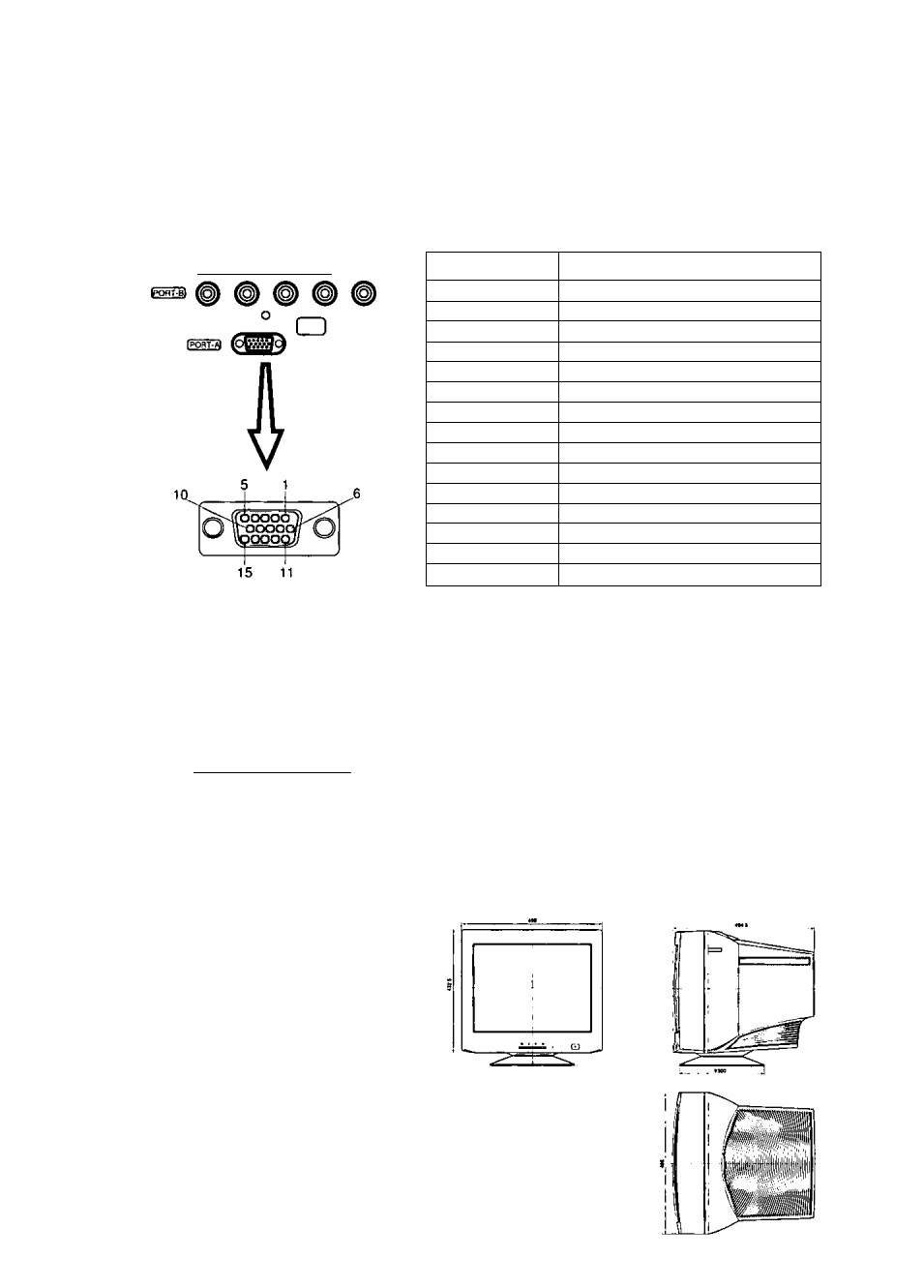
A. Signal connector: 15 pin mini D-Sub (PS / 2 or PC / AT compatible model)
Connect the signal cable to the 15 pin mini D-Sub connector on the display unit.
B. Signal connector: 15 pin D-Sub (Apple computer)
Convert a MAC 15 pin D-Sub connector to a 15 pin mini D-Sub connector using a Panasonic MAC
adapter, and connect it to the 15 pin mini D-Sub connector on the display unit.
< REAR PANEL >
(
rep
I (
greei
^ [
beuei
|
h
-
syhc
1 rvsvMct
Pin assignments of 15 pin mini D-Sub connector
Pin number
Signal name
1
Red video signal
2
Green video signal
3
Blue video signal
4
Ground
5
Ground*
6
Ground for Red video signal
7
Ground for Green video signal
8
Ground for Blue video signal
9
Unused
10
Ground
11
Ground
12
SDA* (Bi-directional Data)
13
Horizontal sync, signal
14
Vertical sync, signal
15
SCL* (Data Clock)
C. Signal connector: BNC connector
*: “VESA”s Display Data Channel (DDC) Standard
Sync on green system
Connect the signal cable to RED, GREEN (sync
ongreen) and BLUE BNC connectors.
Composite sync system
Connect the signal cable to RED, GREEN, BLUE
and H-SYNC (H / V composite) BNC connectors.
[REOl IGREENl (BLUEl (H-SYNCl (V-S
y
HC)
O
□
Separate sync system
Connect the signal cable to RED, GREEN, BLUE
and H-SYNC and V-SYNC BNC connectors.
Note : If your computer’s video output is over
110 MHz, it is recommended that it be
used with the BNC connectors.
External View
Dimensions
Width
: 498 mm (19.6")
Height
: 477.5 mm (18.8")
Depth
: 494.5 mm (19.5")
Base diameter
:
Height without stand: 432.5 mm (17.0")
*an / Tilt range
Up
13 degrees
Down
3 degrees
Left, right :
90 degrees each
••To
U
8