3 calculating fiber link attenuation, Check optical power levels – CANOGA PERKINS 9145E10G Network Interface Device Hardware User Manual
Page 52
Maintenance
9145E10G Ethernet Network Interface Device User’s Manual
Check Optical Power Levels
39/(40 Blank)
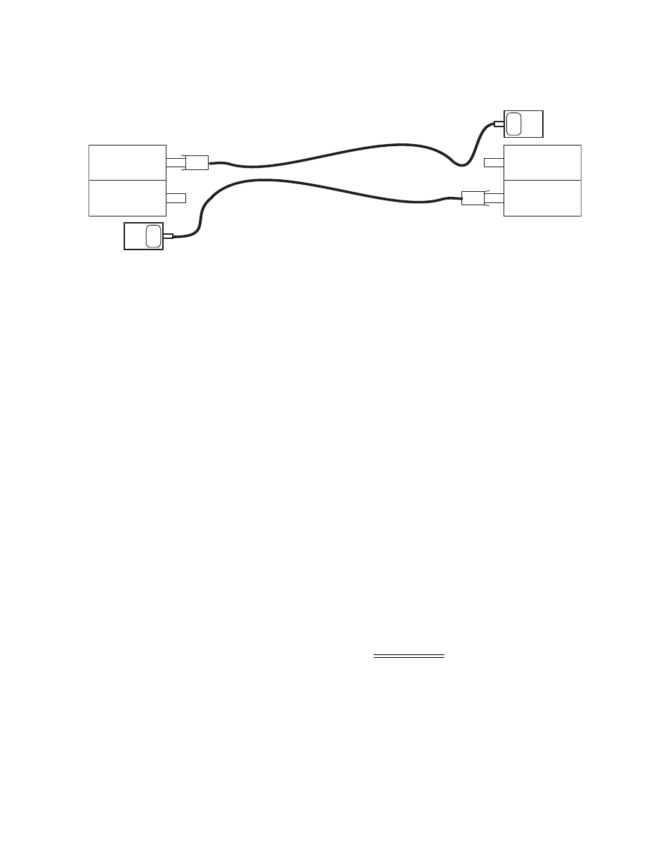
Figure 6-2. Measuring Receiver Input Power
6.2.3 Calculating Fiber Link Attenuation
Link attenuation measurement identifies potential problems with links that are on the threshold of
receiver sensitivity. Measure optical fiber links at the shortest wavelength of operation, as it is the
limiting factor in the loss budget. Use a power meter calibrated for the laser source, then factor in
approximately 1 dB for the connector loss from the patch cables between the 9145E10G and the
local device. (Each fiber connection can generate 0.5 dB of additional loss.)
NOTE: If you cannot determine the Rx sensitivity, contact Canoga Perkins
Technical Support for assistance.
Follow these steps to calculate fiber link attenuation:
1. Determine transmitter output power as described in paragraph 6.2.1 above.
2. Determine receiver input power as described in paragraph 6.2.2 above.
3. Subtract receiver input power from transmitter output power. The result is the fiber link
attenuation.
Transmit Output Power
-7.0 dBm
Receiver Input Power
-28.2 dBm
Fiber Link Attenuation
21.2 dB
FIBER OPTIC
TRANSMITTER
FIBER OPTIC
RECEIVER
OPTICAL
POWER
METER
-24dBm
λ
= 1300 nm
FIBER OPTIC
TRANSMITTER
FIBER OPTIC
RECEIVER
OPTICAL
POWER
METER
-24dBm
λ
= 1300 nm
LOCAL SITE
REMOTE SITE