1 power-up and front panel functions, 1 ethernet management leds, Operation – CANOGA PERKINS 9145E10G Network Interface Device Hardware User Manual
Page 39: Chapter 4 operation
Operation
9145E10G Ethernet Network Interface Device User’s Manual
Power-Up and Front Panel Functions
27
4.1 Power-Up and Front Panel Functions
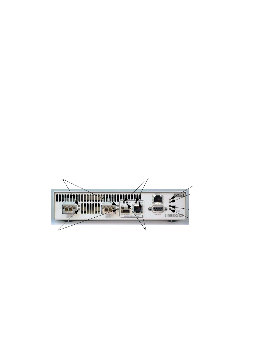
The LEDs on the front panel indicate the system and port status of the 9145E10G (see Figure 4-
1). During power-up, all LEDs on the 9145E10G will light amber. When power-up has been com-
pleted, the LEDs will display status as described in the following paragraphs. Additional informa-
tion about fault conditions appears in the System Alarms and System Status & Configuration
screens (Reference 6913367, 9145E10G NID Software User’s Manual).
Figure 4-1. 9145E10G Status Indicators
4.1.1 Power and Status LEDs
The POWER and STATUS LEDs (see Figure 4-1), located to the right of the console and man-
agement ports, indicate condition and state of the 9145E10G. See Table 4-1 for significance of
LED conditions.
4.1.1 Ethernet Management LEDS
The Link/Activity ( L/A) front panel LED (see Figure 4-1), located to the right of the console and
management ports, indicates the presence of transmit or receive activity. The Speed (SPD) front
LINK/ACTIVITY LED
SPEED LED
POWER LED
STATUS LED
LINK/ACTIVITY LED
SPEED LED
SPEED LED (-527 ONLY)
LINK/ACTIVITY LED (-527 ONLY)
Chapter 4
Operation