2 wall mounting – CANOGA PERKINS 9145E10G Network Interface Device Hardware User Manual
Page 32
9145E10G Ethernet Network Interface Device User’s Manual
Installation
Mounting Options
20
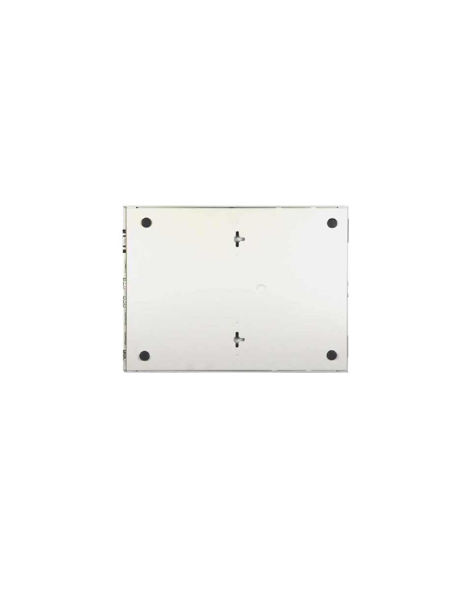
3.3.2 Wall Mounting
CAUTION: Fasteners used for wall mounting of the 9145E10G are required
to withstand a force of 18lbs, applied in any direction. Failure to
meet these requirements could result in damage to the equip-
ment.
The bottom panel of the 9145E10G is designed with keyhole cutouts to accommodate wall
mounting. A template is provided with the Quick-Start Guide so that the installer can precisely
fasten mounting screws onto a wall. Two number 8 screws and wall anchors, which are not pro-
vided by Canoga Perkins, are used for wall mounting. The keyholes are designed so that the
9145E10G unit can be mounted in three positions: with front panel facing the floor, to the right or
to the left (see Figure 3-8).
Figure 3-8. Wall Mounting Cutout Locations
Assure that there is enough unobstructed space around the perimeter of the 9145E10G to allow
for adequate airflow and servicing. Install the 9145E10G on a wall as follows:
1. Tape the template (see Figure 3-9) to the wall, ensuring that the edge of the template cor-
responding to the direction you wish to mount the unit is parallel to the floor and ceiling.
2. Drill a hole through the center of each hole position marker on the template.
3. Remove the template from the wall
4. Install a screw anchor in each drilled hole, then install a #8 screw into each anchor. Leave
the screws protruding from the wall approximately 1/8”.
5. Place the keyholes of the 9145E10G over the screws, then slide the unit down to lock it
into position on the screws.