2 data interface section leds – CANOGA PERKINS 9145E10G Network Interface Device Hardware User Manual
Page 24
9145E10G Ethernet Network Interface Device User’s Manual
Functional Description
LED Indicators
12
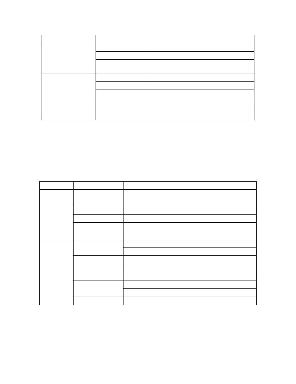
2.7.2 Data Interface Section LEDs
Table 2-4 represents the indications supplied by the SPD and L/A LEDs of the User, Network,
and Multipurpose ports. Indications apply to both UTP, SFP, and XSP LEDs.
Table 2-4. User and Network Port LED Indicators
POWER
Off
Power is off
Green
Power is on
Red
One of the board supply voltages has exceeded a
threshold value
STATUS
Off
No Power
Green
Normal operation
Amber
System self-test in progress
Blinking Amber
System is booting
Red
One of the board supply voltages has exceeded a
threshold value
* Slow Blinking Green means LED toggles between OFF and GREEN approximately once per
second.
LED Name
State
Condition
SPD
Off
Port Disabled
Green
10GBase Full
Amber
System Test
Red
Remote Fault
Blinking Red
Invalid/Unsupported XFP installed
Slow Blinking Green*
Port Enabled but No Link
L/A
Off
No link
No transmit or receive activity
Green
Link on with full duplex
Blinking Green
Transmission or receiving activity with full duplex
Amber
System test
Red
Port Disabled
LLF
Blinking Red
No Link, but transmitting OAM packets in unidirectional mode
* Slow Blinking Green means the LED toggles between OFF and GREEN approximately once per
second.
LED Name
State
Condition