Rane MM 42 User Manual
Page 11
Manual-
for an artist’s hearing difference between right and left ears, for
example) or to process two completely independent mono mixes.
To Link or Unlink an individual processing section:
1. Select the desired processing section.
2. Navigate to the Selected Output(s) field
3. Rotate the DATA control to select between adjusting param-
eters for OUT1+2 (linked) operation, OUT 1 only, or OUT
2 only.
PEQ ON | EQ GAIN FREQ BW (Q)
OUT 1+2| 1 0dB 100Hz 1/3 (4.3)
When OUT1+2 is selected, Output 2’s parameters are set
to match those of Output 1. Note that OUT 2’s settings are not
permanently overwritten. Switching back to OUT 2 restores them
to their previous values.
Bypassing Processing Sections
A wise man once said “it’s not a feature if you can’t turn it
off.” Each processing section in the MM 42 can be turned off,
allowing for quick before-and-after comparisons, or to bypass an
unused section altogether.
To bypass a processing section:
1. Navigate to the status area of the processing section.
2. Rotate the DATA control counter-clockwise until off is dis-
played.
PEQ off| EQ GAIN FREQ BW (Q)
OUT 1+2| 1 0dB 100Hz 1/3 (4.3)
If parameters are unlinked (OUT 1 or OUT 2, instead of
OUT1+2), only the processing section for the currently selected
output is bypassed.
INPUTS dBFS
HIGH/LOW
CUT/SHELF
FILTERS
3-BAND
COMPRESSOR
5-BAND
PARAMETRIC
EQUALIZER
3-BAND
PEAK
LIMITER
OUTPUTS dBu
INPUT
MIXER
OUTPUT
LEVEL
OUTPUT
LEVEL
SUB
BANDPASS
FILTER
–36
–12
–24
–8
–4
10
10
3
1
6
3
1
6
GAIN REDUCTION
dB
A B C D
INPUT
MIXER
INPUT
MIXER
HIGH/LOW
CUT/SHELF
FILTERS
3-BAND
COMPRESSOR
5-BAND
PARAMETRIC
EQUALIZER
3-BAND
PEAK
LIMITER
OUTPUT
LEVEL
OUT 2
SUB
OUT 1
INPUTS
A
B
C
D
+8
–12
–24
0
–3
+4
+8
–12
–24
0
–3
+4
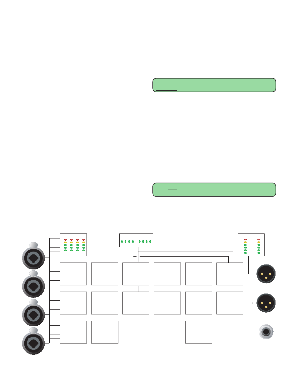
Block Diagram – Main Inputs, Outputs and Sub Output
Signal Processing
Overview
So what does the MM 42 have under the hood you ask?
Plenty! Routing options allow the assignment of any combina-
tion of the four Inputs to any of the three Outputs:
OUT 1, OUT 2 and SUB.
Each of the processing chains for OUT 1 and OUT 2
features (in this order): Shelf/Cut Filters, a 3-band rms Com-
pressor with fully adjustable crossover frequency points, 5-band
fully Parametric EQ, and a 3-band Peak Limiter, also with fully
adjustable crossover frequency points. The SUB output process-
ing chain is completely independent of the main outputs and
features adjustable Low- and High-Cut Filters for maximizing
onstage thump.
Why is the Output Level located before the Limiter?
Placing the Output Level before the Limiter allows you to
turn up a compressed and equalized mix while maintaining the
Limiter’s brick wall protection. Note that there may be some
interaction between the output level and limiter, depending on
how the limiter is set. For example, if the limiter is set up to
catch the occasional peak and you then turn the output level up
by 6 dB, expect to see more limiting as the entire mix is now 6
dB closer to the threshold.
Linking and Unlinking Parameters within Processing
Sections
Parameters within each processing section can be linked
or unlinked, depending on the application. Adjusting param-
eters in linked mode affects both outputs simultaneously and is
particularly useful when working with Stereo mixes, as it allows
you to change one set of parameters and affect both sides of
the mix identically. Unlinking parameters allows you to make
individual adjustments to each side of a stereo mix, (to account