Carrier PREMIERLINK 33CSPREMLK User Manual
Page 7
7
RED
RED
BRN
GRN
FAN
CMP1
CMP2
HS2
HS1
PWR
HS3/EXH/RVS
RED
RED
J8
J1
PWR
CUT
T
O
ISOLA
TE
CONTROLLER
POWER
CUT
FOR DUAL
TRANSFORMER
EQUIPTMENT
RELA
YS
WHT
BLU
YEL
RED
ORN
PNK
PremierLink Connections
40RMQ Connections
CR
W2
R
Y1
Y2
W1
G
C
X
WHT
WHT
IFC C2
C1
40RM, 40RMQ, 40RMS
HEAT ACCESSORY
W2
W1
C
38AQ007
Control
Connections
CR
R
O
W
BL
Y
RED
RED
BRN
GRN
FAN
CMP1
CMP2
HS2
HS1
PWR
HS3/EXH/RVS
RED
RED
J8
J1
PWR
CUT
T
O
ISOLA
TE
CONTROLLER
POWER
CUT
FOR DUAL
TRANSFORMER
EQUIPTMENT
RELA
YS
WHT
BLU
YEL
RED
ORN
PNK
PremierLink Connections
40RM Connections
38AQS008
Terminal
Board (TB)
W2
R
Y1
Y2
W1
G
C
X
WHT
WHT
IFC C2
C1
40RM, 40RMQ, 40RMS
HEAT ACCESSORY
W2
W1
C
W2
R
Y1
Y2
W1
G
C
X
LLSV
CR
CR
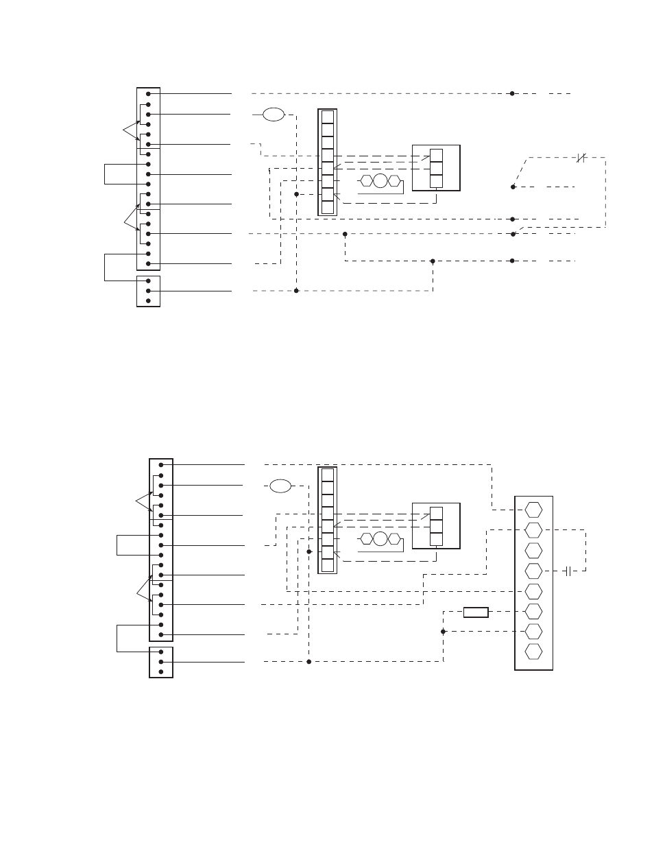
LEGEND
NOTES:
1. Configure AC to “1” for heat pump units.
2. Configure AUXOUT to “3’ for reversing valve.
3. Configure PremierLink control for 2-stage heat and single-stage cool.
4. If IAQ is high priority, wire HS2 to W1. If not, wire HS1 to W1.
Fig. 2G — Typical PremierLink™ Control Wiring — 38AQ007 Units
CR — Control Relay (Field-Supplied)
IAQ — Indoor-Air Quality
IFC — Indoor-Fan Contactor
LEGEND
NOTES:
1. Configure AC to “1” for heat pump units.
2. Configure AUXOUT to “3” for reversing valve.
3. Configure PremierLink control for 2-stage heat and single-stage cool.
4. When using controller for DCV, if IAQ priority is set to HIGH, the controller will use a stage of heat for temperature tempering.
If priority is set to LOW, no tempering will occur. If IAQ is high priority, wire HS2 to W1. If not, wire HS1 to W1.
Fig. 2H — Typical PremierLink Control Wiring — 38AQS008 and 38ARQ008,012 Units
CR
— Control Relay (Field-Supplied)
IFC
— Indoor-Fan Contactor
IAQ
— Indoor-Air Quality
LLSV — Liquid LIne Solenoid Valve