Carrier PREMIERLINK 33CSPREMLK User Manual
Page 10
10
Table 3 — Thermistor Resistance vs Temperature
Values for Space Temperature Sensor,
Supply Air Temperature Sensor, and
Outdoor Air Temperature Sensor
SUPPLY AIR TEMPERATURE (SAT) SENSOR INSTAL-
LATION — The 33ZCSENSAT supply air temperature sensor
is required for controller operation. The sensor consists of a
thermistor encased within a stainless steel probe. The SAT
sensor probe is 6-in. nominal length with 114 in. of unshielded,
2-conductor 18 AWG twisted-pair cables. The sensor tempera-
ture range is –40 to 245 F with a nominal resistance of
10,000 ohms at 77 F. The sensor measures accuracy of ±0.36 F.
The SAT sensor is supplied with a gasket and 2 self-drilling
mounting screws.
NOTE: The sensor must be mounted in the discharge of the
unit, downstream of the cooling coil and heat exchanger. Be
sure the probe tip does not come in contact with any of the
unit surfaces. See Fig. 11 for mounting location.
Do not run sensor or relay wires in the same conduit or race-
way with Class 1 AC service wiring. Do not abrade, cut, or
nick the outer jacket of the cable. Do not pull or draw cable
with a force that may harm the physical or electrical properties.
Avoid splices in any control wiring.
Perform the following steps to connect the SAT sensor to
the PremierLink™ controller:
1. Locate the opening in the control box. Pass the sensor
probe through the hole.
2. Drill or punch a
1
/
2
-in. hole in the supply air duct.
3. Use two field-supplied, self-drilling screws to secure the
sensor probe to the duct.
4. Connect the sensor leads to the PremierLink controller’s
wiring harness J6-3,4 board at the terminals labeled SAT
(ORN) and GND (BRN).
TEMP
(C)
TEMP
(F)
RESISTANCE
(Ohms)
–40
–40
335,651
–35
–31
242,195
–30
–22
176,683
–25
–13
130,243
–20
–4
96,974
–15
5
72,895
–10
14
55,298
–5
23
42,315
0
32
32,651
5
41
25,395
10
50
19,903
15
59
15,714
20
68
12,494
25
77
10,000
30
86
8,056
35
95
6,530
40
104
5,325
45
113
4,367
50
122
3,601
55
131
2,985
60
140
2,487
65
149
2,082
70
158
1,752
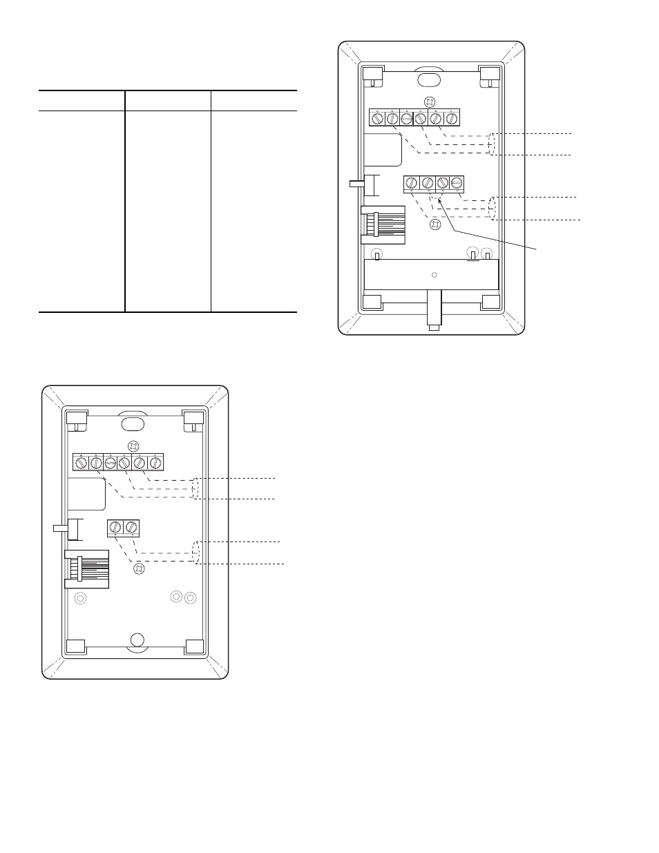
2
3
4
5
6
1
SW1
SEN
SET
Cool
Warm
BRN (GND)
BLU (SPT)
RED(+)
WHT(GND)
BLK(-)
CCN COM
SENSOR WIRING
JUMPER
TERMINALS
AS SHOWN
BLK
(T56)
Fig. 4 — Space Temperature Sensor
Typical Wiring (33ZCT56SPT)
2
3
4
5
6
1
SW1
SEN
BRN (GND)
BLU (SPT)
RED(+)
WHT(GND)
BLK(-)
CCN COM
SENSOR WIRING
Fig. 3 — Space Temperature Sensor
Typical Wiring (33ZCT55SPT)